Sensing techniques using a moving reference

A reference value and reference line technology, applied in the field of sensing technology using mobile references, can solve problems such as loss of memory devices

Pending Publication Date: 2020-07-07
MICRON TECH INC
View PDF3 Cites 0 Cited by
  • Summary
  • Abstract
  • Description
  • Claims
  • Application Information

AI Technical Summary

Problems solved by technology

A volatile memory device such as DRAM may lose its stored state over

Method used


Image

  • Sensing techniques using a moving reference
  • Sensing techniques using a moving reference
  • Sensing techniques using a moving reference

Examples


Embodiment Construction

[0017] A single memory cell can be configured to store one or more bits of digital data as one or more logic states of the memory cell. For a one-bit (eg, two-state) memory cell, the possible logic states may be 0 and 1, for example. For a two-bit (eg, four-state) memory cell, the possible logic states may be 00, 01, 10, and 11. Each such state may be represented by a particular voltage level. Accordingly, determining a logic state stored on a memory cell (eg, during a read operation) may include determining a voltage level associated with the memory cell.

[0018] For memory cells that store a single bit, a single sensing component can be used to compare a signal representative of the state of the memory cell to a single reference value (eg, a reference voltage) to determine the state of the memory cell. If the signal voltage is higher than the reference voltage, the state may be determined as a first state (eg, 1). If the signal voltage is lower than the reference voltage...


PUM


Abstract

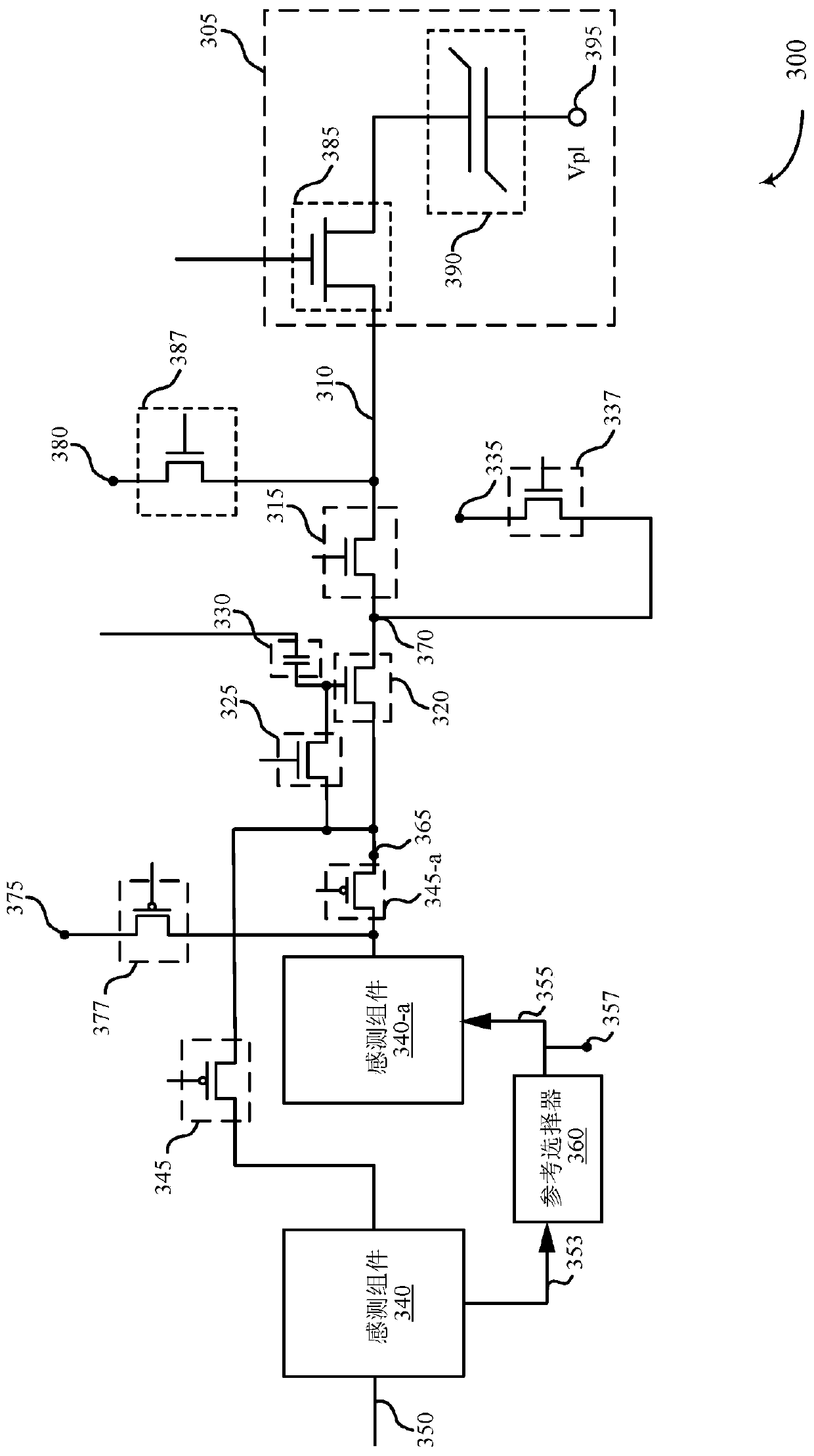
The invention relates to sensing techniques using a moving reference. To sense the memory cell (e.g., to sense the signal associated with the memory cell), a first sense component may compare the signal with a first reference value. A reference selector may select a second reference value based on the comparison of the signal with the first reference value. A second sense component may compare thesignal with the second reference value. The logic state of the memory cell may be determined based on the results of the first comparison and the second comparison.

Description

[0001] cross reference [0002] This patent application claims priority to U.S. Patent Application Serial No. 16 / 232,317, filed December 26, 2018, by Raad et al., entitled SENSING TECHNIQUES USING A MOVING REFERENCE, Said US patent application is assigned to the present assignee and is expressly incorporated herein by reference in its entirety. technical field [0003] The technical field relates to sensing techniques using moving references. Background technique [0004] The following generally relates to a system including at least one memory device, and more particularly to sensing techniques using a moving reference during a read operation of a memory cell. [0005] Memory devices are widely used to store information in various electronic devices such as computers, wireless communication devices, cameras, digital displays, and the like. Information is stored by programming different states of the memory device. For example, binary devices most often store one of two ...

Claims


Application Information

Patent Timeline
IPC IPC(8): G11C8/08G11C8/14G11C7/10
CPCG11C8/08G11C8/14G11C7/1051G11C11/221G11C11/2273G11C11/5657G11C11/565G11C11/4091G11C11/4094G11C2211/5634
Inventor G·B·雷德J·F·施雷克
Owner MICRON TECH INC
Why Eureka
Try Eureka