Electroluminance lighting device embedding touch function
A lighting device and luminescent technology, applied in the direction of lighting devices, components of lighting devices, circuit layout, etc., can solve problems such as blocking of light-emitting areas of lighting devices, mechanical problems of assembly structures, etc.
- Summary
- Abstract
- Description
- Claims
- Application Information
AI Technical Summary
Problems solved by technology
Method used
Image

Examples
no. 1 approach
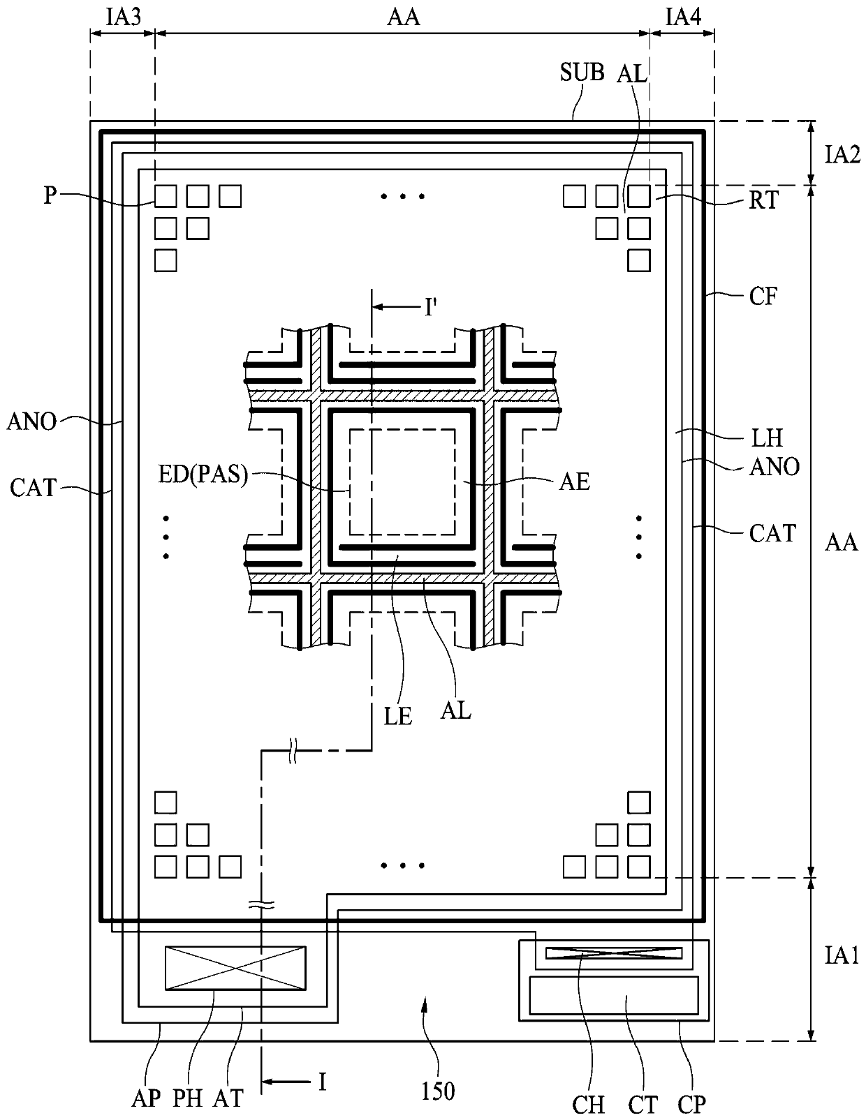
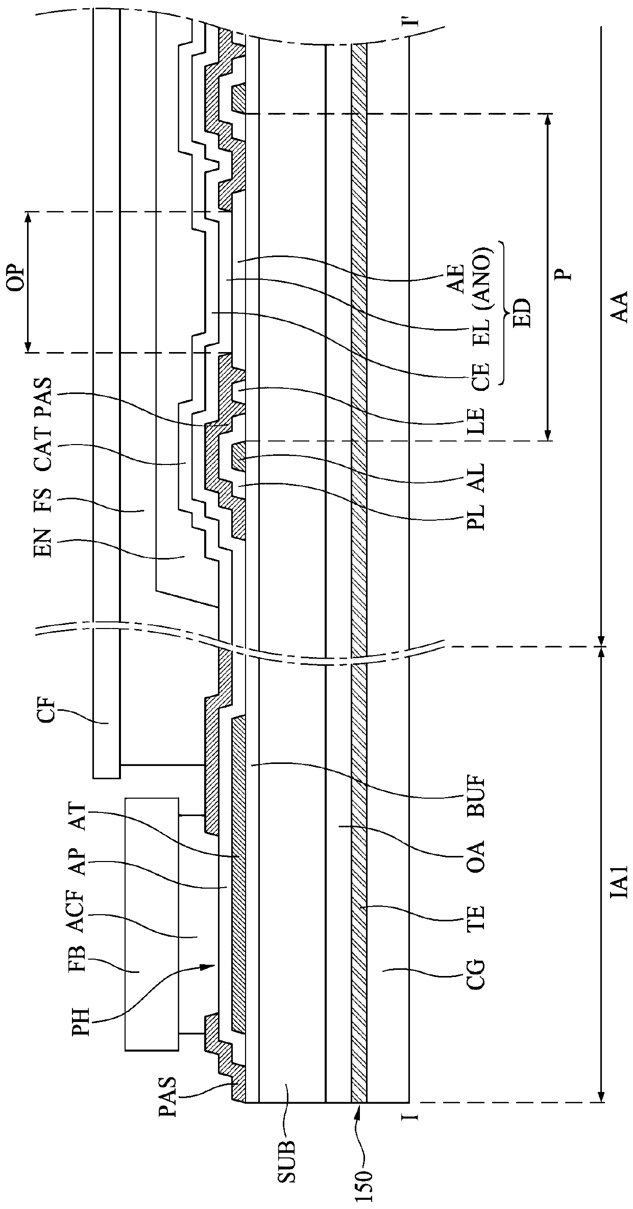
[0033] In the following, refer to figure 1 and figure 2 , the electroluminescent lighting device according to the first embodiment of the present disclosure will be described. figure 1 is a plan view illustrating an electroluminescent lighting device embedded with a touch layer according to an embodiment of the present disclosure. figure 2 is along figure 1 The cross-sectional view taken along the cutting line II' shows the structure of the electroluminescent lighting device embedded with the touch layer according to the first embodiment of the present disclosure. In this embodiment, the lighting device is an organic light emitting lighting device, but is not limited thereto.
[0034] refer to figure 1 and figure 2 , the electroluminescent lighting device according to the first embodiment of the present invention includes a substrate SUB, a wiring RT, an auxiliary line AL, an anode layer ANO, a cathode layer CAT, a light emitting element ED, a first pad AP, a second pa...
no. 2 approach
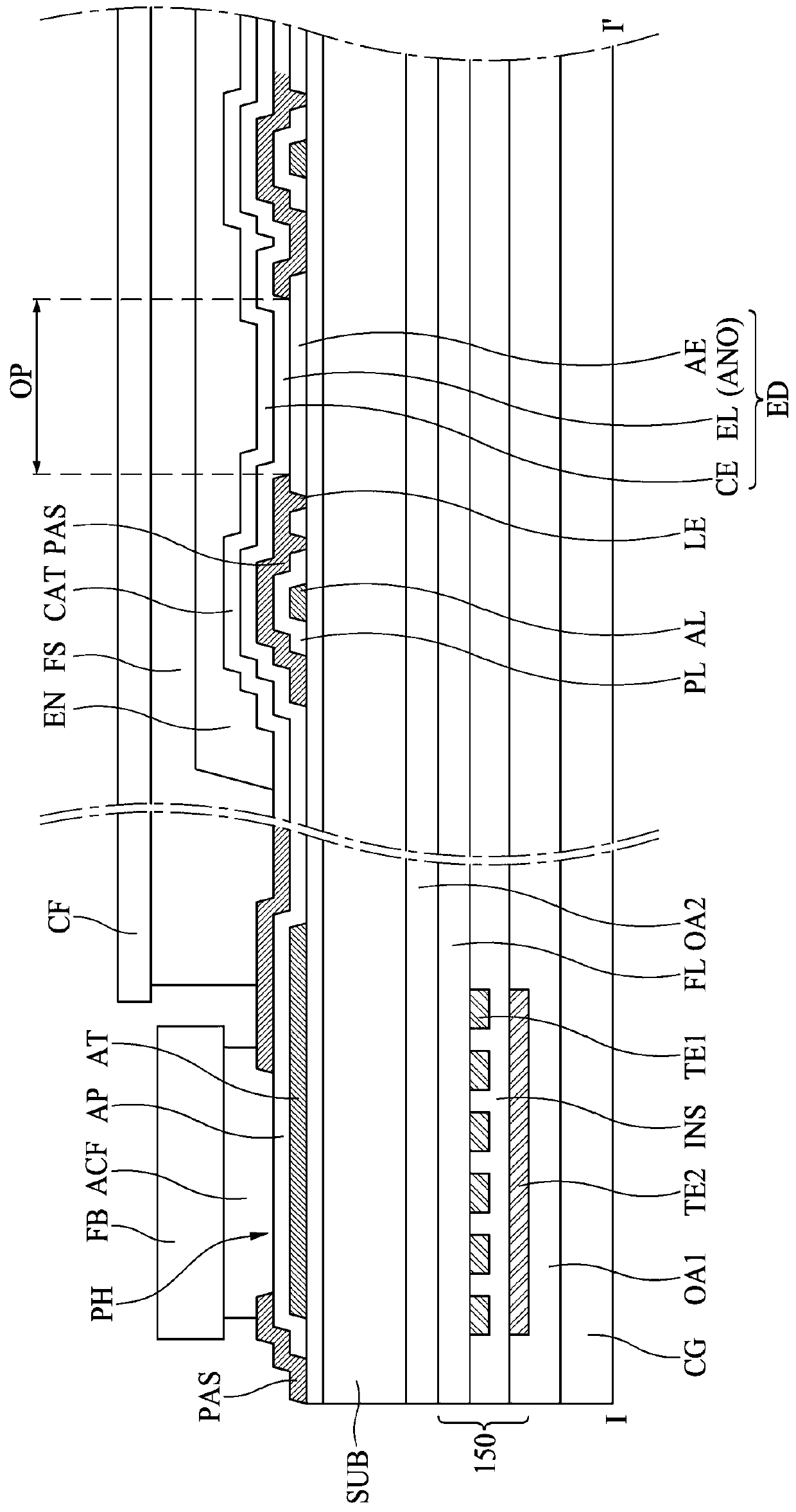
[0064] In the following, refer to figure 1 and image 3 , a second embodiment of the present disclosure will be described. image 3 is along figure 1 The cross-sectional view taken along the cutting line II' of , shows the structure of the electroluminescent lighting device embedded with the touch layer according to the second embodiment of the present disclosure.
[0065] refer to image 3 , according to the second embodiment of the present invention, the electroluminescent lighting device embedded with a touch layer includes a substrate SUB, a wiring RT, an auxiliary line AL, an anode layer ANO, a cathode layer CAT, a light emitting element ED, a first pad AP, a second Two pads CP, a cover film CF and a touch layer 150 . Basically, the structure of the touch layer-embedded electroluminescent lighting device according to the second embodiment is the same as that of the first embodiment. The difference lies in the detailed configuration and location of the touch layer 150...
no. 3 approach
[0071] Below, refer to figure 1 and Figure 4 , a third embodiment of the present disclosure will be described. Figure 4 is along figure 1 The cross-sectional view taken along the cutting line II' of , shows the structure of the electroluminescent lighting device embedded with the touch layer according to the third embodiment of the present disclosure.
[0072] refer to Figure 4 , according to the third embodiment of the present invention, the electroluminescent lighting device embedded with a touch layer includes a substrate SUB, a wiring RT, an auxiliary line AL, an anode layer ANO, a cathode layer CAT, a light emitting element ED, a first pad AP, a second Two pads CP, a cover film CF and a touch layer 150 . The basic structure of the touch layer-embedded electroluminescent lighting device according to the third embodiment is very similar to that of the first and second embodiments. The difference lies in the configuration and location of the touch layer 150 . In the...
PUM
 Abstract
Description
Claims
Application Information
 - R&D
- Intellectual Property
- Life Sciences
- Materials
- Tech Scout
- Unparalleled Data Quality
- Higher Quality Content
- 60% Fewer Hallucinations
Browse by: Latest US Patents, China's latest patents, Technical Efficacy Thesaurus, Application Domain, Technology Topic, Popular Technical Reports.
© 2025 PatSnap. All rights reserved.Legal|Privacy policy|Modern Slavery Act Transparency Statement|Sitemap|About US| Contact US: help@patsnap.com