
Valve units, pump heads and pump units

A valve device and valve seat technology, which is applied to valve devices, cocks including cut-off devices, pumps, etc., can solve the problems of dead zone reduction and difficulty in increasing the ultimate vacuum degree, and achieve the effect of increasing the ultimate vacuum degree

Active Publication Date: 2022-02-11
爱发科机工株式会社
View PDF10 Cites 0 Cited by
  • Summary
  • Abstract
  • Description
  • Claims
  • Application Information

AI Technical Summary

Problems solved by technology

However, the existing valve mechanism has the problem that it is impossible to reduce the dead space and it is difficult to increase the ultimate vacuum degree.

Method used


Image

  • Valve units, pump heads and pump units
  • Valve units, pump heads and pump units
  • Valve units, pump heads and pump units

Examples


Embodiment

[0189] Table 1 shows the measurement results of the ultimate pressure of the pump device equipped with the pump head 60 according to the present embodiment together with the measurement results obtained by using a conventional pump device.

[0190] In Table 1 below, a diaphragm-type dry vacuum pump manufactured by ULVAC Co., Ltd., model number DA-241S, was prepared as a pump device having a one-stage compression structure of a conventional product.

[0191] A pump unit in which the pump head of a diaphragm type dry vacuum pump model DA-241S manufactured by ULVAC Corporation was replaced with the pump head 60 of this embodiment was prepared as a one-stage compression structure equipped with the pump head 60 of this embodiment. pump unit.

[0192] A diaphragm-type dry vacuum pump model DA-121D manufactured by ULVAC Co., Ltd. was prepared as a pump device having a two-stage compression structure of an existing product.

[0193] A pump unit in which the pump head of a diaphragm t...


PUM


Abstract

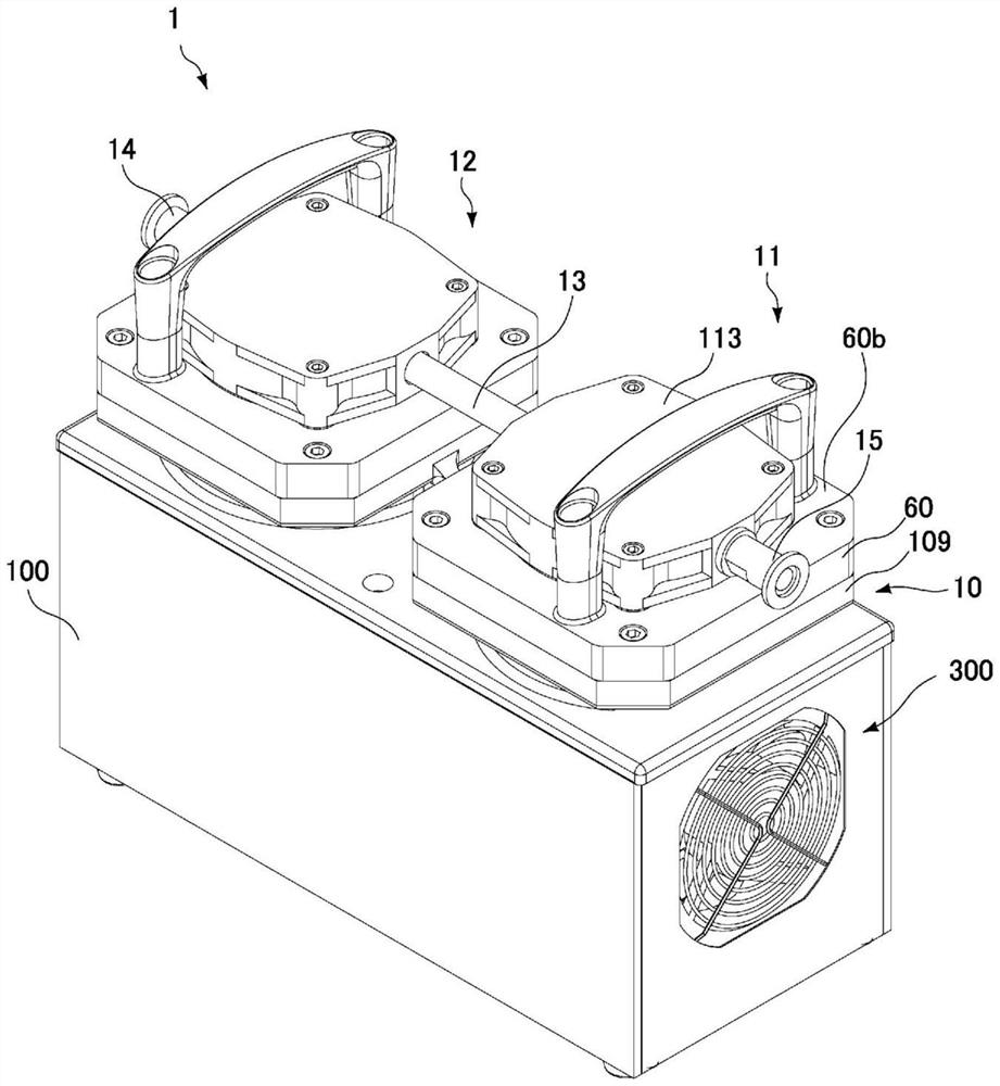
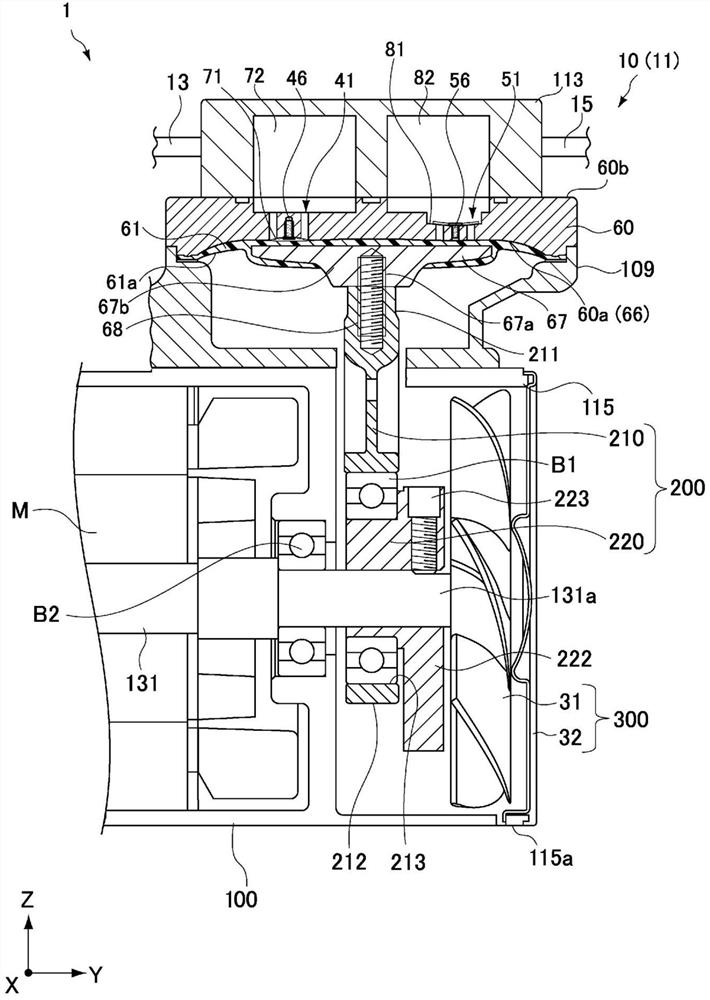
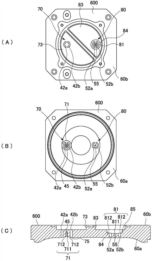
A valve device according to one aspect of the present invention includes a valve seat, a valve member, and a fastener. The valve seat is formed by a conical concave surface having a bottom formed with a connection hole and a plurality of ventilation holes formed around the connection hole. The valve member has a supporting portion and a plurality of valve portions, the supporting portion faces the bottom; the plurality of valve portions has a plurality of slits extending radially from the outer side of the supporting portion, and the plurality of The valve portion faces the plurality of vent holes and is elastically deformable. The fastener is connected with the connection hole and fixes the supporting part on the valve seat.

Description

technical field [0001] The present invention relates to a valve device for suction and exhaust, a pump head, and a pump device having the pump head. Background technique [0002] A diaphragm pump, which is one type of positive displacement pump, moves a fluid by combining a valve mechanism that controls the opening and closing of a fluid flow path and a reciprocating motion of a diaphragm. A check valve is used in the valve mechanism, and as the check valve, a plate-shaped valve having a valve tongue structure (hereinafter referred to as a tongue valve) and a circular valve having a circular structure are often used. [0003] Tongue valves generally use steel and other materials with relatively strong spring stress. [0004] In a valve mechanism using a tongue valve, one end of the tongue valve is fixed to a valve seat by a set screw. The other end of the tongue valve is a free end capable of bidirectional movement between a closed position in contact with the seat surface...

Claims


Application Information

Patent Timeline
Patent Type & Authority Patents(China)
IPC IPC(8): F16K15/14F04B45/04
CPCF16K5/16F04B43/02F04B53/10F04B45/04F16K15/14F04B53/1072F04B53/108
Inventor 铃木雄吾
Owner 爱发科机工株式会社
Learn More