

Air blast cooling rotary vane roller pump
A technology of cold rotary vane and roller pumps, applied in the field of variable capacity pumps, can solve the problems of direct-coupled pumps such as temperature rise, large frictional resistance, and large power consumption, and achieve the goals of increasing ultimate vacuum, reducing temperature rise, and reducing power Effect
Inactive Publication Date: 2003-12-31
王安大
View PDF2 Cites 1 Cited by
- Summary
- Abstract
- Description
- Claims
- Application Information
AI Technical Summary
Problems solved by technology
[0006] The purpose of the present invention is to reduce the ultimate vacuum of the pump due to the harmful space of the oil-free lubricating pump, and the frictional resistance is large, the temperature of the direct-coupled pump is increased, and the power consumption is large. The forced air-cooled double-arc inner cavity rotary vane roller column pump
Method used
View moreImage
Smart ImageViewing Examples

Examples
Embodiment Construction
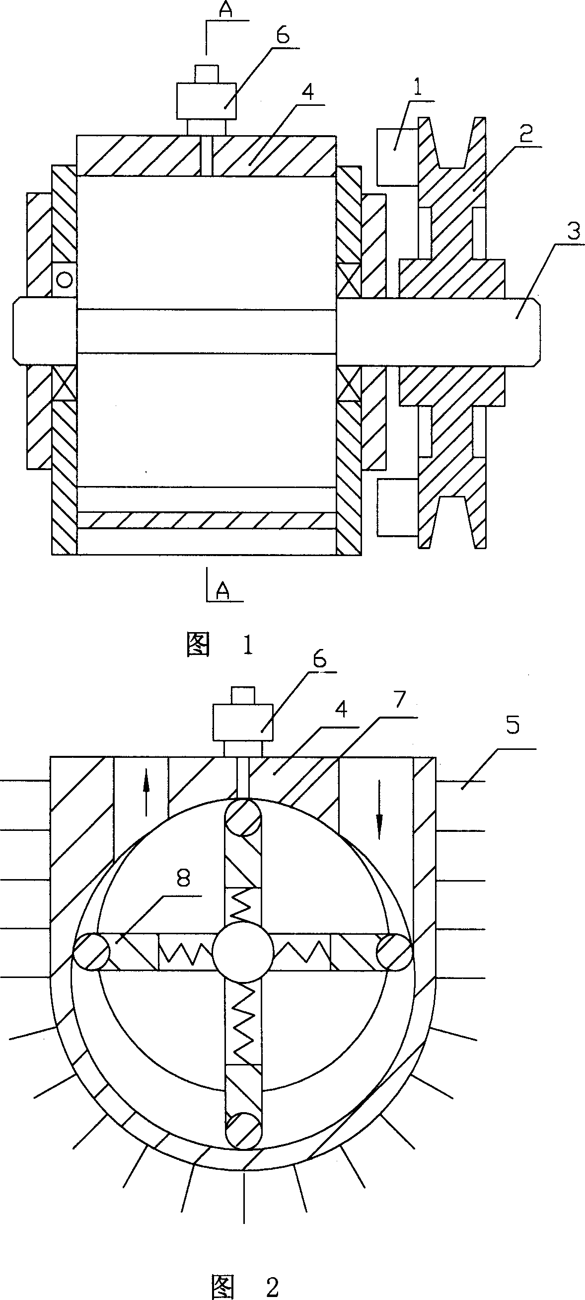
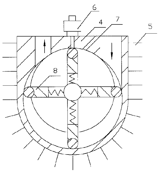
[0031] Process a small circular arc (7) equal to the rotor radius in the single cylindrical hole of the pump body cavity, and the length of the small circular arc is advisable to eliminate the harmful space of the rotor body and the pump. A needle valve type drip cup (6) is installed on the pump body (4) to regulate the oil intake, to ensure the lubrication in the pump, but the pump does not inject oil. A pulley (2) is installed on the rotor shaft (3) of the pump, a number of vanes (1) are cast on the rim end surface of the pulley, and axial cooling fins (5) are cast on the outer surface of the pump body. When the pulley rotates, the blades Forced air cooling of the pump body.
Login to View More PUM
 Abstract
The forced wind cooled rotating sheet roller pump is used as vacuum pump or vacuum-pressure composite air pump. It has cast radiating fins in the outer surface for expanding heat radiating area, fan in the belt pulley for forced cooling of the pump, double-arc inner cavity to eliminate harmful space inside the pump and raise extreme vacuum degree, and needle valve type oil cup to reach boundary lubricating effect. The pump has simple structure, low cost, high energy saving effect and no pollution.
Description
Technical field [0001] The invention belongs to variable capacity pumps and can be used to manufacture vacuum pumps and vacuum pressure composite air pumps. Background technique [0002] Existing rotary vane vacuum pumps and rotary vane roller pumps (Patent No. 93233179.3, ZL99232727.x) are mainly composed of a pump body, a rotor, front and rear end covers, and a combined rotary vane assembly assembled by installing a cylinder in a concave groove of the rotary vane. slice composition. Install a rotor eccentrically in the pump chamber, the outer circle of the rotor is tangent to the inner surface of the pump chamber. Space, where the gas cannot be discharged from the pump chamber under the exhaust pressure, but is squeezed into the suction chamber by the rotary vane through the gap between the rotor and the pump body, so the existence of harmful space reduces the ultimate vacuum of the pump and increases power consumption . [0003] The oil-sealed rotary vane vacuum pump u...
Claims
Login to View More Application Information
Patent Timeline
 IPC IPC(8): F04C18/344F04C25/02
Inventor王安大
Owner王安大