A medical device for exercising leg muscles

An exercise device and muscle technology, applied in the directions of muscle training equipment, gymnastics equipment, sports accessories, etc., can solve the problems of single exercise method, can not meet the exercise needs, reduce the recovery effect of leg muscles, etc., and achieve the effect of improving the recovery effect.

Active Publication Date: 2021-09-24
毛玉景
View PDF8 Cites 1 Cited by
  • Summary
  • Abstract
  • Description
  • Claims
  • Application Information

AI Technical Summary

Problems solved by technology

[0002] With the continuous development of medical technology, the cure rate of patients is increasing year by year. Many patients with leg diseases or injuries cannot perform normal walking or other actions immediately after treatment, and often need rehabilitation training for leg muscles. Through A series of leg muscle training can restore the patient's leg to the state before the injury, so that the patient can perform normal walking or other actions. However, the current medical leg muscle training device has a single training method, which is often stepped on by bending the knee Exercising force for muscle training cannot meet the training needs of various leg muscles and reduce the recovery effect of leg muscles

Method used


Image

  • A medical device for exercising leg muscles
  • A medical device for exercising leg muscles
  • A medical device for exercising leg muscles

Examples


specific Embodiment approach 1

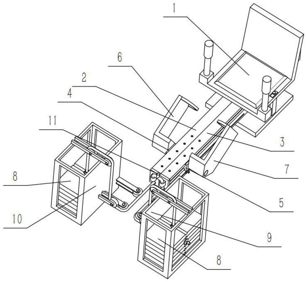
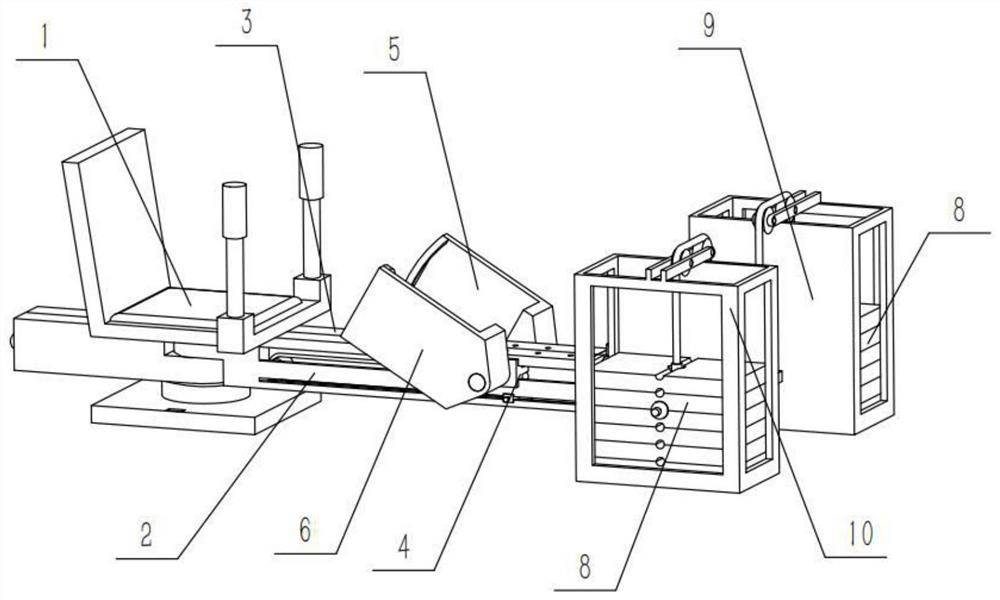
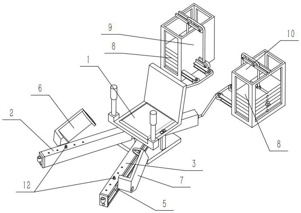
[0042] Combine below Figure 1-17 Describe this embodiment, a medical leg muscle training device, including a counterweight 8, a fixed fork 11 and a positioning pin 12, the toy injection molding machine also includes a riding mechanism 1, a right sliding frame mechanism 2, a left sliding frame mechanism 3. Right slide mechanism 4, left slide mechanism 5, right force applying mechanism 6, left force apply mechanism 7, counterweight sliding frame mechanism I9 and counterweight sliding frame mechanism II10, the right sliding frame mechanism 2 and the left sliding frame mechanism 3 are all rotatably connected to the lower end of the ride mechanism 1, and the right sliding mechanism 4 and the left sliding mechanism 5 are slidingly connected in the right sliding frame mechanism 2 and the left sliding frame mechanism 3 respectively, so The right side force applying mechanism 6 and the left side force applying mechanism 7 are respectively hinged on the right side sliding mechanism 4 a...

specific Embodiment approach 2

[0045] Combine below Figure 1-17 Describe this embodiment, this embodiment will further explain Embodiment 1, described riding mechanism 1 comprises seat 1-1, arm bar 1-2, rotating shaft 1-3, base 1-4, limit column 1-5, Limiting groove 1-6 and anti-rotation bar 1-7, described holding bar 1-2 is provided with two, and two holding bars 1-2 are respectively fixedly connected to the left and right ends of seat 1-1 front end, and described The rotating shaft 1-3 is fixedly connected to the lower end of the seat 1-1, the limiting column 1-5 is slidably connected to the middle part of the left end of the seat 1-1, and the limiting groove 1-6 is provided with two, two Limiting grooves 1-6 are respectively arranged in the middle of the left and right ends of the base 1-4, the lower end of the limiting column 1-5 is inserted into a certain limiting groove 1-6, and the anti-rotation rod 1-7 is fixedly connected to The lower side of the middle part of the front end of the seat 1-1, the ...

specific Embodiment approach 3

[0047] Combine below Figure 1-17 This embodiment will be described. This embodiment will further illustrate Embodiment 1 or 2. The right sliding frame mechanism 2 includes a right sliding frame 2-1, a fixed pipe I2-2, a through hole I2-3, and a right end Plate 2-4, sliding chamber I 2-5 and sliding chamber II 2-6, the right sliding frame 2-1 is rotatably connected to the rotating shaft 1-3, and the rear end of the right sliding frame 2-1 is provided with Fixing hole I2-2, the right end plate 2-4 is fixedly connected to the front end of the right sliding frame 2-1, and the sliding chamber I2-5 and sliding chamber II2-6 are respectively arranged on the right sliding frame 2- 1. On the upper and lower sides of the front end, a plurality of through holes I2-3 are provided, and the plurality of through holes I2-3 are uniformly arranged on the front end of the right sliding frame 2-1, and the right sliding mechanism 4 is slidably connected to the sliding In cavity I2-5 and sliding...


PUM


Abstract

The present invention relates to the technical field of leg muscle training equipment, in particular to a medical leg muscle training device, which includes a counterweight, a fixed fork and a positioning pin, a riding mechanism, a right sliding frame mechanism, a left sliding Frame mechanism, right sliding mechanism, left sliding mechanism, right force applying mechanism, left force applying mechanism, counterweight sliding frame mechanism Ⅰ and counterweight sliding frame mechanism Ⅱ, right sliding frame mechanism and left sliding frame mechanism Both are rotatably connected to the lower end of the riding mechanism, the right side sliding mechanism and the left side sliding mechanism are slidingly connected in the right side sliding frame mechanism and the left side sliding frame mechanism respectively, and the right side force applying mechanism and the left side force applying mechanism are hinged on the right side respectively. On the side sliding mechanism and the left sliding mechanism, the two counterweights are slidably connected in the counterweight sliding frame mechanism Ⅰ and counterweight sliding frame mechanism Ⅱ. This device can meet the exercise needs of various muscles of the legs and improve the leg Muscle recovery effect.

Description

technical field [0001] The invention relates to the technical field of leg muscle training equipment, in particular to a medical leg muscle training device. Background technique [0002] With the continuous development of medical technology, the cure rate of patients is increasing year by year. Many patients with leg diseases or injuries cannot perform normal walking or other actions immediately after treatment, and often need rehabilitation training for leg muscles. Through A series of leg muscle training can restore the patient's leg to the state before the injury, so that the patient can perform normal walking or other actions. However, the current medical leg muscle training device has a single training method, which is often stepped on by bending the knee Applying force for muscle training cannot meet the exercise needs of various muscles of the legs and reduce the recovery effect of the muscles of the legs. Contents of the invention [0003] The purpose of the prese...

Claims


Application Information

Patent Timeline
Patent Type & Authority Patents(China)
IPC IPC(8): A63B23/04A63B21/062A63B22/18A63B22/20
CPCA63B22/18A63B22/203A63B23/04A63B23/0417A63B21/0628
Inventor 毛玉景焦占峰邵莉于长春
Owner 毛玉景
Why Eureka
Try Eureka