All-working-condition gas-liquid separation device for satellite storage tank

A gas-liquid separation device and a technology of full working conditions, applied in the aerospace field, can solve the problems of increasing the cost of satellites, separate installation space, and inability to perform separation functions, and achieve the effect of simple structure, high structural strength, and good flexibility

Inactive Publication Date: 2020-07-10
BEIJING INST OF CONTROL ENG
View PDF6 Cites 3 Cited by
  • Summary
  • Abstract
  • Description
  • Claims
  • Application Information

AI Technical Summary

Problems solved by technology

The spiral channel type gas-liquid separation can only play a separation role in the case of a large flow rate, and cannot play a separation role when the flow rate or pressure difference is small
At present, the existing gas-liquid separator is based on surface tension separation. It is installed on the gas outlet pipeline of the tank, which requires a separate installation space and increases the cost of the satellite. It is installed inside the tank for exhaust-type on-orbit filling technology. The advanced gas-liquid separation device is the key to realize repeated replenishment of satellite propellant

Method used


Image

  • All-working-condition gas-liquid separation device for satellite storage tank
  • All-working-condition gas-liquid separation device for satellite storage tank
  • All-working-condition gas-liquid separation device for satellite storage tank

Examples


Embodiment

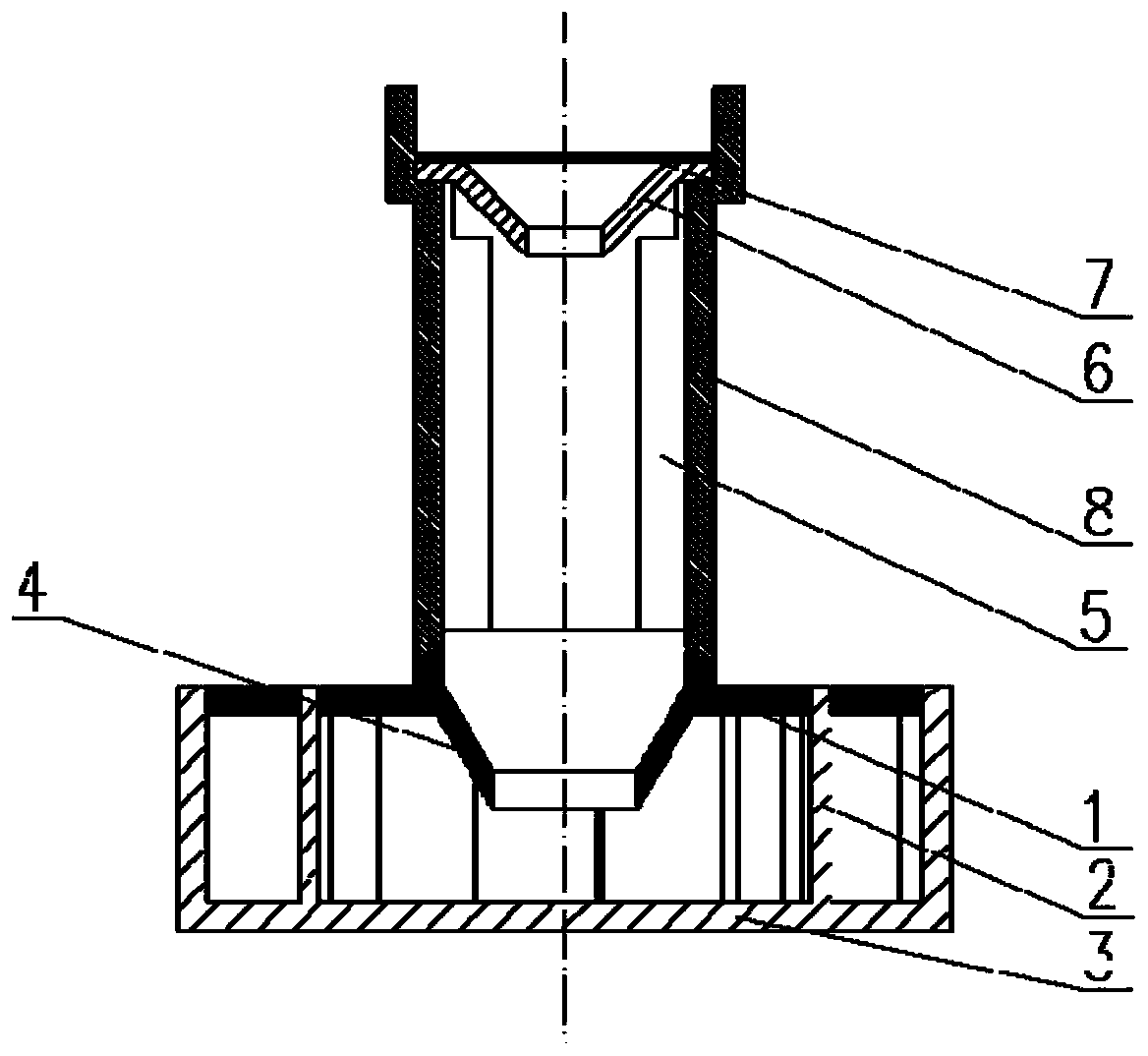
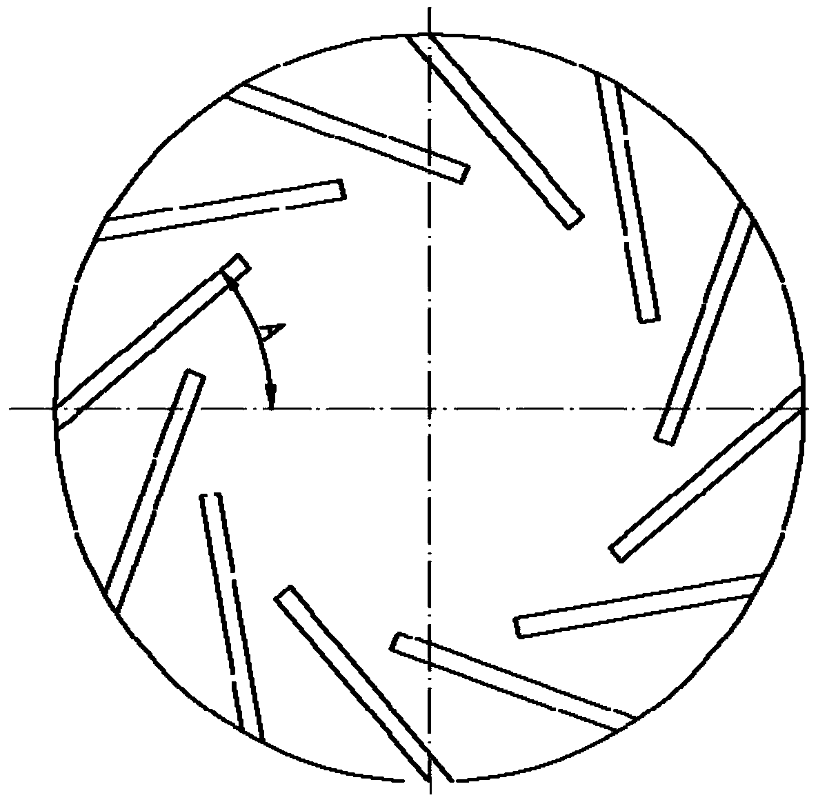
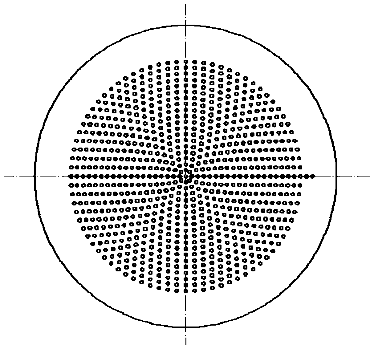
[0027] Such as figure 1 As shown, a gas-liquid separation device under full working conditions of a satellite storage tank includes: an upper cover plate 1, a centrifugal blade 2, a lower cover plate 3, a lower partition plate 4, a deflector plate 5, an upper partition plate 6, and a perforated plate 7. Cylindrical cavity 8; a plurality of centrifugal blades 2 are evenly distributed along the circumference, and are installed between the upper cover 1 and the lower cover 3; the cylindrical cavity 8 is installed in the center of the upper cover 1, and the cylindrical cavity 8 is connected to the centrifugal The cavities between the blades 2 are connected; the lower partition 4 is fixed on the lower end of the cylindrical cavity 8, and the deflector 5 is uniformly fixed on the inner wall of the cylindrical cavity 8 along the circumferential direction; the perforated plate 7 is installed on the upper partition 6, The perforated plate 7 and the upper baffle 6 are installed on the u...


PUM

PropertyMeasurementUnit
diameteraaaaaaaaaa
angleaaaaaaaaaa
thicknessaaaaaaaaaa

Abstract

An all-working-condition gas-liquid separation device of a satellite storage tank comprises an upper cover plate (1) and the like. A plurality of centrifugal blades (2) are evenly distributed in the circumferential direction and installed between the upper cover plate (1) and a lower cover plate (3). A cylindrical cavity (8) is formed in the center of the upper cover plate (1) and is communicatedwith a cavity between the centrifugal blades (2); a lower partition plate (4) is fixed to the lower end of the cylindrical cavity (8), and flow guide plates (5) are evenly fixed to the inner wall faceof the cylindrical cavity (8) in the circumferential direction. A perforated plate (7) is installed on an upper partition plate (6), and the perforated plate (7) and the upper partition plate (6) areinstalled at the upper end of the cylindrical cavity (8). Effective separation of gas and liquid in the microgravity environment of a satellite propellant storage tank is achieved through the principle that centrifugal force and surface tension drive fluid, liquid clamping in the exhaust process of the storage tank is avoided, and the device is simple in structure, free of moving parts, easy to machine, light in weight, high in reliability and capable of meeting the use requirements of various space environments.

Description

technical field [0001] The invention relates to a full working condition gas-liquid separation device of a satellite storage tank, which belongs to the field of aerospace technology. Background technique [0002] Satellite on-orbit refueling technologies can be divided into pressurized, vented and through-type refueling, etc. Vented refueling needs to be exhausted through the gas port of the tank to ensure that the internal pressure of the tank will not continue to increase and reduce the propellant. Repeat the filling pressure. Installing a gas-liquid separator at the gas port of the storage tank is a key device of the exhaust-type on-rail filling method. At present, there is no mature gas-liquid separator device in China. On the ground, gas-liquid separation can be achieved by gravity separation, centrifugal separation and other technologies. When the satellite is in orbit, the effect of gravity disappears, and the effect of surface tension is significant, so the gas-liq...

Claims


Application Information

Patent Timeline
Patent Type & Authority Applications(China)
IPC IPC(8): B01D50/00
CPCB01D50/20
Inventor 刘锦涛李永陈磊毕强李文丁凤林万磊宋飞梁红义周超
Owner BEIJING INST OF CONTROL ENG
Why Eureka
Try Eureka