Forming die for large hoop

A technology for forming molds and backing plates, which is used in forming tools, manufacturing tools, metal processing equipment, etc., can solve the problems of manual removal, low production efficiency, affecting production efficiency, etc., and achieves a reduction in overall width and improves production efficiency. Effect

Inactive Publication Date: 2020-07-10
HEFEI ZHENGTE MACHINERY CO LTD
View PDF0 Cites 1 Cited by
  • Summary
  • Abstract
  • Description
  • Claims
  • Application Information

AI Technical Summary

Problems solved by technology

[0004] The object of the present invention is to provide a molding die for large hoops. By setting two L-shaped modules, the upper mold is pressed down, and the L-shaped modules are rotated to squeeze the hoop sideways, which solves the problem of the existing lower The problem of low mold adaptability that affects production efficiency; by setting the upper mold as a wedge block and two side modules; solves the problem of low production efficiency that needs to be removed manually after the existing hoop is formed

Method used


Image

  • Forming die for large hoop
  • Forming die for large hoop
  • Forming die for large hoop

Examples


Embodiment 1

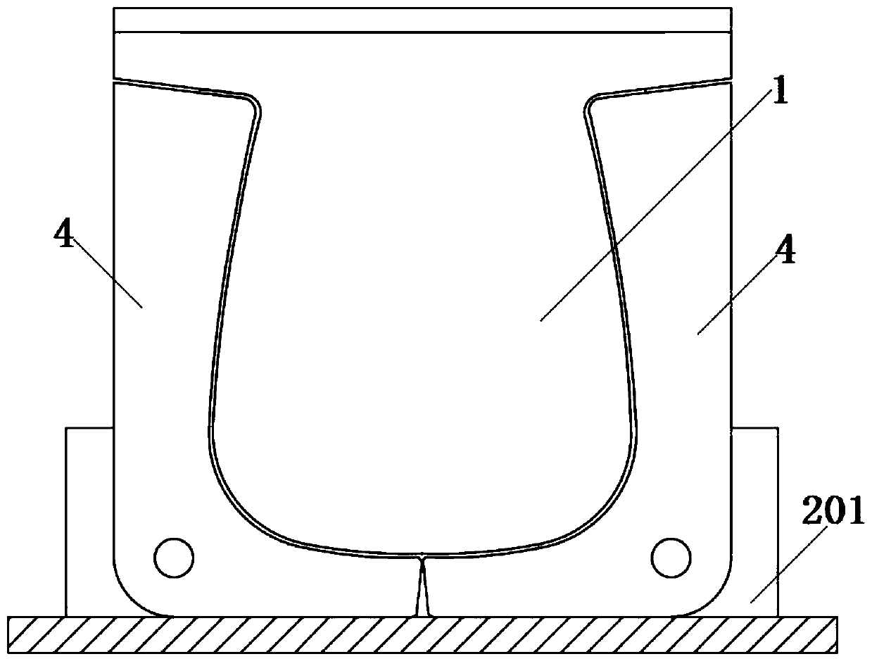
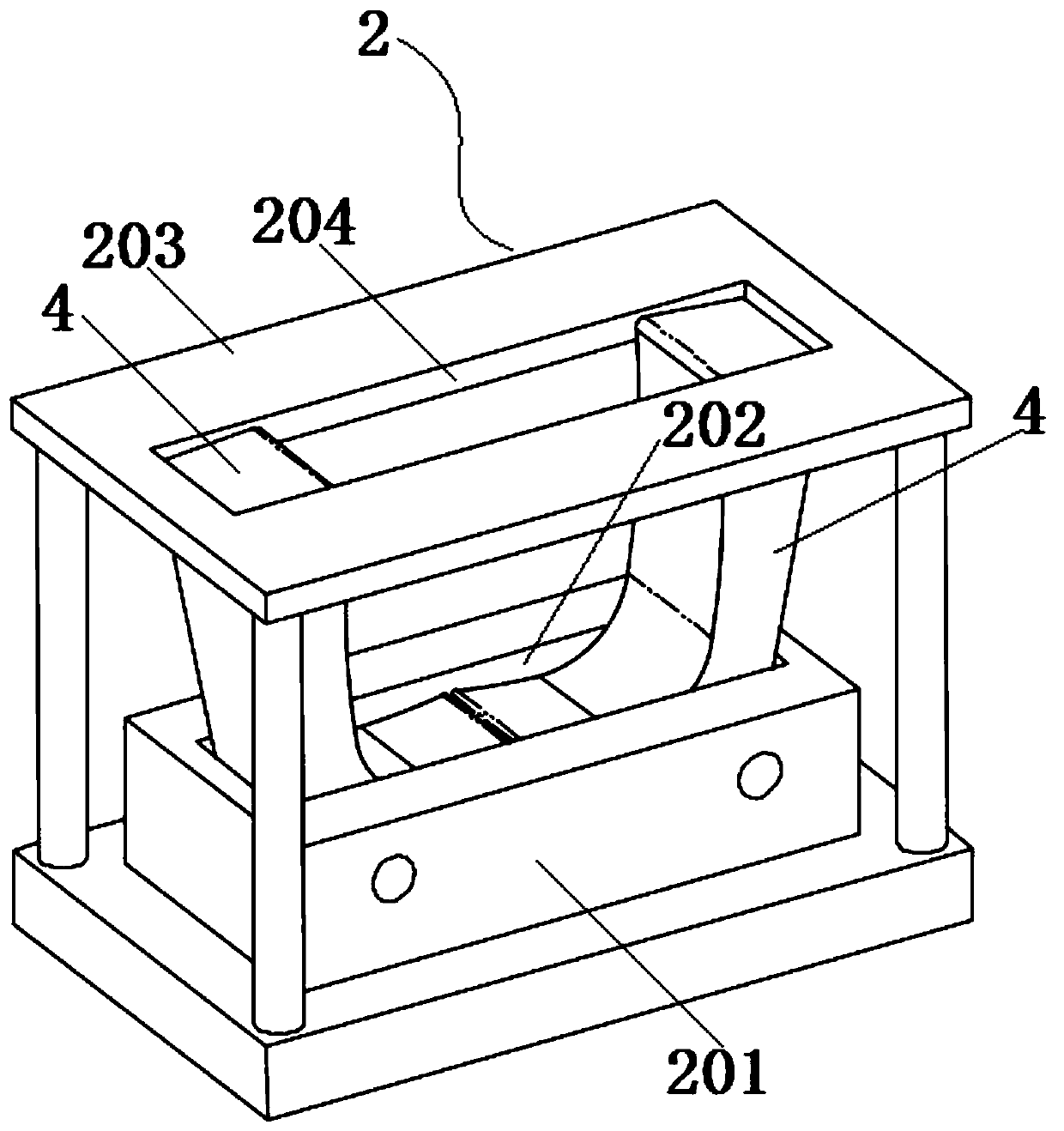
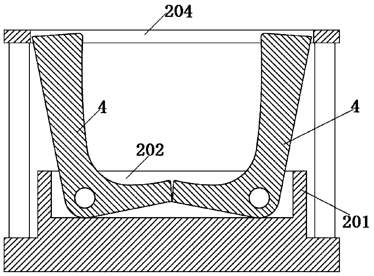
[0031] see figure 1 As shown, the present invention is a molding die for a large hoop, including an upper die 1 and a lower die 2; the cross-sectional shape of the upper die 1 in the vertical direction is U-shaped, and the width of the upper die 1 from top to bottom Gradually increase, so that the hoop after punching becomes a U-shaped structure, and the width of the hoop opening is smaller than the overall width of the hoop.

[0032] Such as Figure 5 As shown, the surface of the upper mold 1 is rounded, and the upper surface of the upper mold 1 is connected with an upper backing plate 11; the upper surface of the upper backing plate 11 is connected with a telescopic device 3.

[0033] Telescopic device 3 can be air cylinder or hydraulic cylinder, and telescopic device 3 can be provided with two, and two telescopic devices 3 are installed and fixed by mounting plate 301, offers through hole on mounting plate 301, and the telescopic end of telescopic device 3 passes through t...

Embodiment 2

[0042] Such as Figure 5-7 As shown, the upper mold 1 includes a wedge block 101; the wedge block 101 is an isosceles trapezoidal structure, and the lower surface of the wedge block 101 is a curved surface; the upper surface of the wedge block 101 is welded or threaded side by side with a pin shaft 104; the upper end of the pin shaft 104 runs through the upper The backing plate 11; the pin shaft 104 is set with a spring 105, and the lower end of the spring 105 abuts against the upper surface of the upper backing plate 11, and under the action of the spring 105, the upper surface of the wedge block 101 remains in a state of abutting against the lower surface of the upper backing plate 11 .

[0043]Side modules 102 are slidably connected to both sides of the wedge block 101;

[0044] The upper end of the side module 102 is welded with a bending block 103, and the side module 102 and the bending block 103 can also be an integral structure; Dovetail slots or T-shaped slots are p...


PUM


Abstract

The invention discloses a forming die for a large hoop, and relates to the technical field of dies. The forming die comprises an upper die and a lower die; the section of the upper die is in a U shape, and the width is gradually increased from top to bottom; the lower die comprises a fixed block; the fixed block is rotatably connected with two L-shaped modules; the two L-shaped modules are oppositely arranged, and fit the side surface of the upper die; the upper die comprises a wedge block; pin shafts are fixed to the upper surface of the wedge block side by side; the upper ends of the pin shafts penetrate through an upper padding plate, and springs sleeve the upper ends of the pin shafts; two side surfaces of the wedge block are slidably connected with side modules; bending blocks are fixed to the upper ends of the side modules; and the upper surfaces of the bending blocks are slidably connected with the lower surface of the upper padding plate. By arranging the two L-shaped modules,through pressing of the upper die, the L-shaped modules are used for laterally extruding the hoop, and the problem that the production efficiency is affected due to low adaptability of an existing lowdie is solved; and the upper die is arranged as the wedge block and the two-side modules, and the problems that an existing hoop is required to be taken down manually after being formed, and the production efficiency is low are solved.

Description

technical field [0001] The invention belongs to the technical field of moulds, in particular to a molding die for large hoops. Background technique [0002] A hoop is a component that hugs or hoops another material with one material. It belongs to a fastener and has a wide range of applications in industry. The arc-bent shape of the hoop is mainly determined by the mold. The design specifications of the hoop die and the materials selected directly affect the product quality of the hoop from the die. Most of the existing hoops are semicircular, and the hoop die usually adopts a lower mold and an upper mold corresponding to the radian, and the flat iron is bent into a desired shape by mutual punching of the upper mold and the lower mold. [0003] However, some existing hoops with special shapes, such as U-shaped hoops with an opening gap smaller than the width, will be stuck on the upper die after stamping and forming, and need to be removed manually, resulting in low product...

Claims


Application Information

Patent Timeline
Patent Type & Authority Applications(China)
IPC IPC(8): B21D37/10B21D45/04
CPCB21D37/10B21D45/04
Inventor 孙健
Owner HEFEI ZHENGTE MACHINERY CO LTD
Why Eureka
Try Eureka