Reciprocating jaw type crusher for sintered bricks

A jaw crusher, reciprocating technology, applied in grain processing, etc., can solve problems such as environmental pollution, increased production costs, and a large amount of dust, and achieve the effects of improving the operating environment, improving crushing efficiency, and increasing utilization.

Active Publication Date: 2015-09-02
ZHENGZHOU UNIV
View PDF7 Cites 6 Cited by
  • Summary
  • Abstract
  • Description
  • Claims
  • Application Information

AI Technical Summary

Problems solved by technology

The movable jaw of the existing jaw crusher adopts a motor, and the eccentric wheel is driven by the belt to complete the crushing action between the movable jaw and the static jaw. The mechanical safety performance is low, and the crushing effect is not ideal. Broken aggregates will be splashed out, and a large amount of dust will be generated during the crushing process, which will cause serious environmental pollution and cause problems such as low utilization rate of fired bricks.
[0003] In the existing crushing jaw structure design, due to its relatively fixed structure, it is impossible to carry out targeted design according to the characteristics of the crushed aggregate. Therefore, a large number of needle-like and flake-like particles are likely to be produced during the crushing process of sintered bricks.
Sintered brick aggregates with a large number of needle-like and flake-like particles are used as recycled aggregates to configure concrete. The basic mechanical properties such as compression resistance and splitting of recycled brick aggregate concrete are poor, which restricts the use of recycled brick aggregate concrete. application
If the fired brick aggregate with a large number of needle-like and flake-like particles is processed twice, it will increase the production cost, which is not conducive to the resource utilization of fired bricks

Method used


Image

  • Reciprocating jaw type crusher for sintered bricks

Examples


Embodiment 2

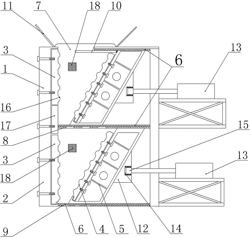
[0028] Embodiment two: see figure 1 , the structure of this embodiment is basically the same as that of Embodiment 1, and the similarities will not be repeated. The difference is that the static jaw plate 3 in the crushing chamber 1 is a vertically split structure, and it also includes a belt There are point-type static jaw plates 17 of point-type crushing jaws evenly distributed on the bottom plate in a dot shape, and the static jaw plate 17 is located at the lower part of the static jaw plate with the tooth-type crushing jaws 16 .

[0029] In the present invention, the function of the crushing bin body 1 is to preliminarily crush the sintered bricks, and the discharge particle size is 30-40 mm.

[0030] ①Setting and function of the static jaw plate: According to the requirements for the discharge particle size, and fully considering the characteristics of high porosity and low strength of the sintered brick, the crushing chamber body and the static jaw plate adopt a split ar...


PUM


Abstract

The invention relates to a crusher of sintered bricks in building waste. A reciprocating jaw type crusher for sintered bricks comprises a crushing bin body I, a crushing bin body II, crushing devices and reciprocating power mechanisms, wherein the crushing bin body I and the crushing bin body II are longitudinally laminated and arranged; the crushing devices are arranged in each crushing bin body in a matched mode; the reciprocating power mechanisms drive the crushing devices; the crushing devices comprise static jaw plates, movable jaws and movable jaw plates, wherein the static jaw plates are fixedly arranged on one side surfaces in the crushing bin bodies; the movable jaws correspond to the static jaw plates and are matched with and in sliding fit with the crushing bin bodies; the movable jaw plates are fixed on the movable jaws; the driving ends of the reciprocating power mechanisms are in connection driving with the movable jaws. The crusher is reasonable in structure design, is high in sintered brick utilization ratio, can control the crushing and discharge particle diameter easily, can obviously reduce the content of needle-shaped or flaky aggregate after discharging, so that the regenerated aggregate can be well adaptive to regenerated concrete preparation and other fields of engineering construction.

Description

technical field [0001] The invention relates to a device for crushing sintered bricks in construction waste, in particular to a reciprocating jaw crusher for sintered bricks. Background technique [0002] The jaw crusher is a crushing chamber composed of two jaw plates, the movable jaw and the static jaw. It simulates the movement of the two jaws of animals to complete the material crushing operation. It is widely used in mine smelting, building materials, roads, railways, water conservancy and chemical industry. Crushing of various ores and bulk materials in the industry. The movable jaw of the existing jaw crusher adopts a motor, and the eccentric wheel is driven by the belt to complete the crushing action between the movable jaw and the static jaw. The mechanical safety performance is low, and the crushing effect is not ideal. Broken aggregates will be splashed out, and a large amount of dust will be generated during the crushing process, which will cause serious environ...

Claims


Application Information

Patent Timeline
Patent Type & Authority Applications(China)
IPC IPC(8): B02C1/04B02C23/04B02C23/08
Inventor 高丹盈景嘉骅周潇左祥祥
Owner ZHENGZHOU UNIV
Why Eureka
Try Eureka