Device and method for manufacturing mould of mini-sized impeller with high height-thickness ratio

A miniature, impeller technology, applied in the direction of manufacturing tools, forging/pressing/hammer devices, forging/pressing/hammering machinery, etc., can solve the problems of unsuitable batch manufacturing, less machinable materials, and low processing efficiency, and achieve good results Comprehensive mechanical properties, improved surface quality, and convenient die replacement

Active Publication Date: 2014-02-26
HARBIN INST OF TECH
View PDF10 Cites 6 Cited by
  • Summary
  • Abstract
  • Description
  • Claims
  • Application Information

AI Technical Summary

Problems solved by technology

[0003] The purpose of the present invention is to solve the problems of high manufacturing cost, low processing efficiency, less machinable materials and unsuitable batch manufacturing in the existing processing technology

Method used


Image

  • Device and method for manufacturing mould of mini-sized impeller with high height-thickness ratio
  • Device and method for manufacturing mould of mini-sized impeller with high height-thickness ratio
  • Device and method for manufacturing mould of mini-sized impeller with high height-thickness ratio

Examples


specific Embodiment approach 1

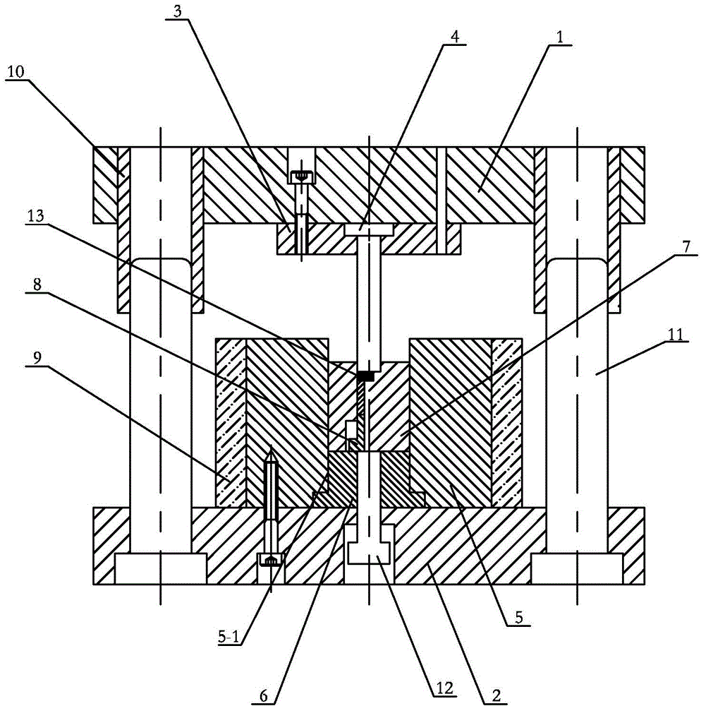
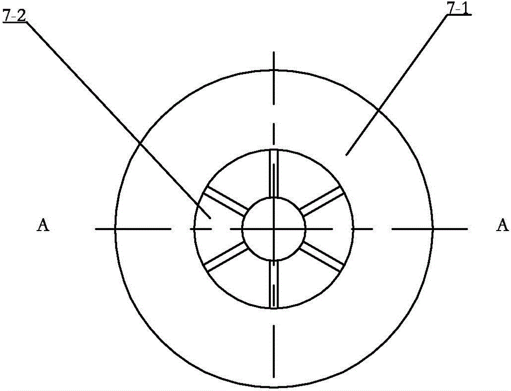
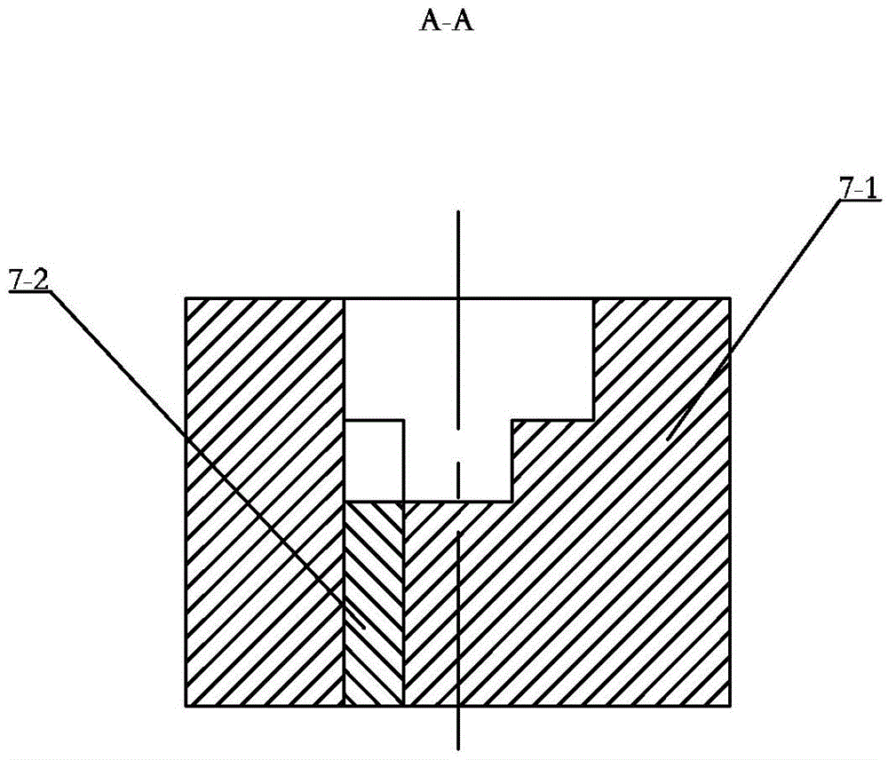
[0025] Specific implementation mode one: combine figure 1 and figure 2 Describe this embodiment, this embodiment includes upper mold base 1, lower mold base 2, punch fixing plate 3, punch 4, die fixing plate 5, die backing plate 6, insert type die 7, ejector pin 8. Heating ring 9, ejection screw 12, multiple guide sleeves 10 and multiple guide pillars 11, the upper mold base 1 and the lower mold base 2 are arranged in parallel up and down, and multiple guide sleeves are arranged around the upper mold base 1 10. One end of each guide post 11 is set on the bottom end surface of the lower mold base 2, the other end of each guide post 11 can be slidably set in a guide sleeve 10, and the punch 4 is set on the punch fixing plate 3 On the top, the punch fixing plate 3 is fixed on the bottom end surface of the upper die base 1, the die fixing plate 5 is fixed on the lower die base 2, the die fixing plate 5 is provided with a die placement hole 5-1, the die The backing plate 6 is se...

specific Embodiment approach 2

[0033] Specific implementation mode two: combination figure 1 The present embodiment will be described. The punch fixing plate 3 of the present embodiment is fixed to the bottom end surface of the upper die base 1 by fastening screws. With such a setting, the connection is convenient. Other compositions and connections are the same as in the first embodiment.

specific Embodiment approach 3

[0034] Specific implementation mode three: combination figure 1 The present embodiment will be described. The die fixing plate 5 of the present embodiment is fixed to the lower die base 2 with fastening screws. With such a setting, the connection is convenient. Other compositions and connections are the same as those in the second embodiment.


PUM


Abstract

The invention relates to a device and a method for manufacturing a mould of a mini-sized impeller with high height-thickness ratio, and relates to a device and a method for the mould of the mini-sized impeller with high height-thickness ratio. The device and method solve the problems of high manufacturing cost, low processing efficiency, less processing material and unsuitability for batch manufacturing realization in the prior art. The device is characterized in that an upper mould base and a lower mould base are parallelly arranged top and bottom; a punching head is arranged on a punching head fixed plate; a concave mould fixed plate is fixed on the lower mould base; a concave mould shim plate is arranged in a concave mould installation plate; an embedded lump type concave mould is arranged in the concave mould installation hole; an ejector rod is arranged in the embedded lump type concave mould; an ejecting screw sequentially penetrates through the lower mould base and the concave mould shim plate from bottom to top to support against the lower end surface of the ejector rod. The method comprises the following steps of: 1, placing a blank into a cavity, and heating to the mould forging temperature of the blank; 2, filling the blank into the cavity of the embedded lump type concave mould; 3, reaching the set load of a pressing machine, maintaining pressure, and then unloading to completely form the mini-sized impeller with high height-thickness ratio. The device and method which are disclosed by the invention are used for manufacturing the mini-sized impeller with high height-thickness ratio.

Description

technical field [0001] The invention relates to a mold device and method for manufacturing a micro-impeller, in particular to a mold device and method for manufacturing a micro-impeller with a high aspect ratio. Background technique [0002] Micro-impellers are widely used in micro-power moulds, such as micro-generators and micro-impeller pumps. The key component is the micro-impeller with a large height-thickness ratio. The micro-impeller with a large height-thickness ratio is of great importance to the efficiency, life and stability of the entire micro-power mould. influences. The thickness of these microblades is generally on the order of submillimeters, and the height can reach millimeters or even several millimeters, and the height-thickness ratio is generally greater than 3. Therefore, it is of great significance to process high-quality, low-cost micro-impeller components with a large height-to-thickness ratio. At present, micro-impeller components with high height-t...

Claims


Application Information

Patent Timeline
Patent Type & Authority Applications(China)
IPC IPC(8): B21J13/02B21J5/02
Inventor 王春举单德彬王传杰徐杰郭斌
Owner HARBIN INST OF TECH
Why Eureka
Try Eureka