Electrical equipment part assembling workbench
A part assembly, electric power technology, applied in the field of electric and electrical equipment parts assembly workbench, can solve the problems of inconvenient installation, large volume, inconvenient observation, etc., and achieve the effects of convenient observation, simple operation, and convenient irradiation observation.
- Summary
- Abstract
- Description
- Claims
- Application Information
AI Technical Summary
Problems solved by technology
Method used
Image

Examples
Embodiment 1
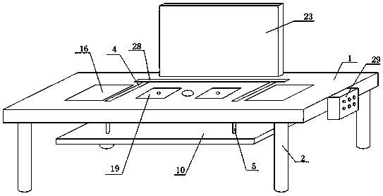
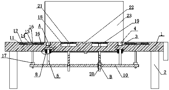
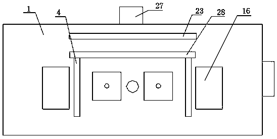
[0031] refer to Figure 1-7 , a workbench for assembling parts of electric power equipment, comprising a table top 1, four symmetrically arranged support legs 2 are fixedly installed on the bottom of the table top 1, a U-shaped through groove 3 is opened on the top of the table top 1, and the U-shaped through groove 3 slides Two symmetrical vertical rods 4 are connected, one end of the two vertical rods 4 is fixedly installed with the same horizontal rod 28, the top of the table 1 is provided with an illuminating light 22, and the bottom of the vertical rod 4 is rotatably connected with two symmetrically arranged supports The rod 5, the support rod 5 is threadedly connected with the table top 1, the bottom ends of the four support rods 5 are rotatably connected with the same positioning plate 10, the top of the table board 1 is slidably connected with a panel 19, and the top of the panel 19 is threadedly connected with a push rod 20, The push rod 20 is rotatably connected with...
Embodiment 2
[0042] refer to Figure 1-7 , an assembly workbench for electric and electrical equipment parts, comprising a table top 1, four symmetrically arranged support legs 2 are welded on the bottom of the table top 1, and a U-shaped through groove 3 is opened on the top of the table top 1, and the U-shaped through groove 3 is slidingly connected There are two symmetrical vertical rods 4, one end of the two vertical rods 4 is welded with the same horizontal rod 28, the top of the table 1 is provided with an illuminating light 22, and the bottom of the vertical rod 4 is rotatably connected with two symmetrically arranged support rods 5 , the support rods 5 are threadedly connected with the table top 1, the bottom ends of the four support rods 5 are rotatably connected with the same positioning plate 10, the top of the table board 1 is slidably connected with a panel 19, and the top of the panel 19 is threadedly connected with a push rod 20, and the push rod 20 is rotatably connected wi...
PUM
 Abstract
Description
Claims
Application Information
 - Generate Ideas
- Intellectual Property
- Life Sciences
- Materials
- Tech Scout
- Unparalleled Data Quality
- Higher Quality Content
- 60% Fewer Hallucinations
Browse by: Latest US Patents, China's latest patents, Technical Efficacy Thesaurus, Application Domain, Technology Topic, Popular Technical Reports.
© 2025 PatSnap. All rights reserved.Legal|Privacy policy|Modern Slavery Act Transparency Statement|Sitemap|About US| Contact US: help@patsnap.com