

Dry dock track mounting method
An installation method and dry dock technology, applied in the field of track installation, can solve the problems of small maintenance space, firm fixation of pillars, high stability requirements, and fast construction speed, so as to improve stability and installation efficiency, and ensure the quality of track installation. Effect
- Summary
- Abstract
- Description
- Claims
- Application Information
AI Technical Summary
Problems solved by technology
Method used
Image

Examples
Embodiment approach 1
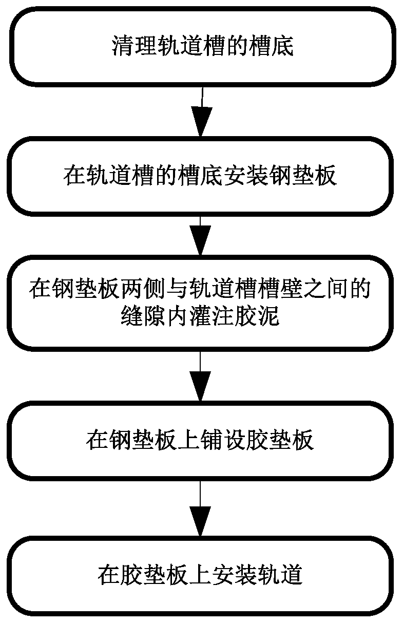
[0031] Such as figure 1 As shown, this embodiment discloses a dry dock track installation method, including the following steps: step 1, cleaning the bottom of the track groove; step 2, installing a steel backing plate on the bottom of the track groove; Pour cement into the gap between both sides of the plate and the groove wall of the track groove; step 4, lay the rubber backing plate on the steel backing plate; step 5, install the track on the rubber backing plate.
[0032] The invention ensures the quality of the track installation and improves the stability and efficiency of the track installation on the premise of simplifying the track installation process.
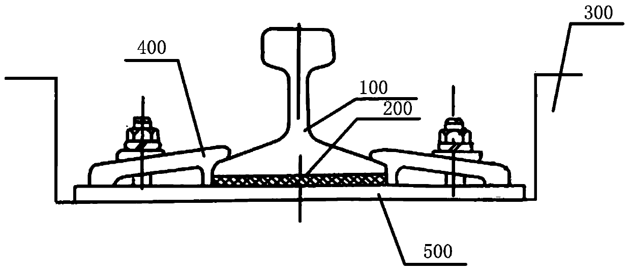
[0033] Such as figure 2 As shown, the steel backing plate of this embodiment is installed at the groove bottom of the track groove, the rubber backing plate is installed on the steel backing plate, the track is installed on the rubber backing plate, and the pressure plate fixes the track and the steel backing plate...
Embodiment approach 2
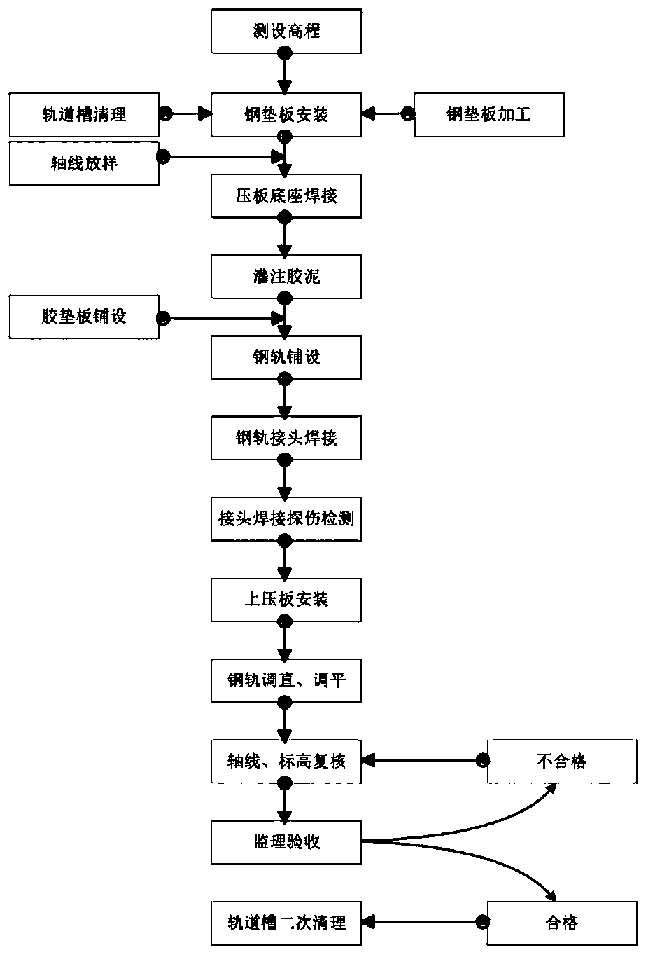
[0035] This embodiment discloses a dry dock track installation method, which includes the following steps: Step 1, cleaning the bottom of the track groove; Step 2, installing a steel backing plate on the bottom of the track groove; Step 3, installing the steel backing plate on the steel backing plate and Weld several pressure plate bases parallel to the track axis, and several pressure plate bases are symmetrically fixed on both sides of the track axis; step 4, pour cement into the gap between the two sides of the steel backing plate and the groove wall of the track groove; step 5, in the steel Lay the rubber pad on the backing plate; step 6, install the track on the rubber pad, install a pressing plate on each pressing plate base, and use multiple pressing plates to fix a section of track.
[0036] Step 1 is specifically: chiseling off loose concrete and laitance on the concrete surface of the track groove, removing floating ash, and removing accumulated water. Step 2 is spec...
Embodiment approach 3
[0038] This embodiment discloses a dry dock track installation method, which includes the following steps: step 1, cleaning the bottom of the track groove; step 2, installing a steel backing plate on the bottom of the track groove; step 3, installing steel backing plates on both sides of the steel backing plate Pour cement into the gap between the wall of the track groove and the groove; step 4, weld a number of pressure plate bases on the steel backing plate and parallel to the axis of the track, and several pressure plate bases are symmetrically fixed on both sides of the track axis; Lay the rubber pad on the backing plate; step 6, install the track on the rubber pad, install a pressing plate on each pressing plate base, and use multiple pressing plates to fix a section of track.
[0039] Step 1 is specifically: chiseling off loose concrete and laitance on the concrete surface of the track groove, removing floating ash, and removing accumulated water. Step 2 is specifically ...
PUM
 Abstract
Description
Claims
Application Information