
A temporary pier support method for a long-span steel-concrete composite girder cable-stayed bridge

A temporary pier, large-span technology, applied in cable-stayed bridges, bridge construction, bridges, etc., can solve problems such as large fluctuations, small safety risks, and tower deflection changes, and achieve simple steps, high connection positioning accuracy, and stress clear effect

Active Publication Date: 2021-10-19
陕西交控通宇交通研究有限公司
View PDF0 Cites 0 Cited by
  • Summary
  • Abstract
  • Description
  • Claims
  • Application Information

AI Technical Summary

Problems solved by technology

However, the addition of temporary piers will cause significant changes in the deflection of the tower, which will increase the difficulty of controlling the alignment of the long-span steel-concrete composite girder cable-stayed bridge. Load, and affected by the horizontal component force of the cable stay and temperature, the improper design of the connection between the main girder and the temporary pier will generate a large horizontal force. Therefore, there is a lack of a temporary connection with high construction accuracy, small safety risks, and strong operability. Temporary piers of long-span steel-concrete composite girder cable-stayed bridge

Method used


Image

  • A temporary pier support method for a long-span steel-concrete composite girder cable-stayed bridge
  • A temporary pier support method for a long-span steel-concrete composite girder cable-stayed bridge
  • A temporary pier support method for a long-span steel-concrete composite girder cable-stayed bridge

Examples


Embodiment Construction

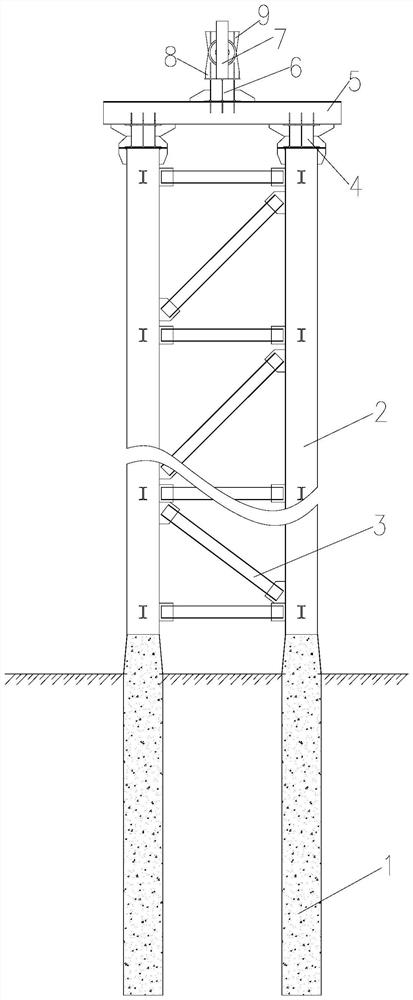
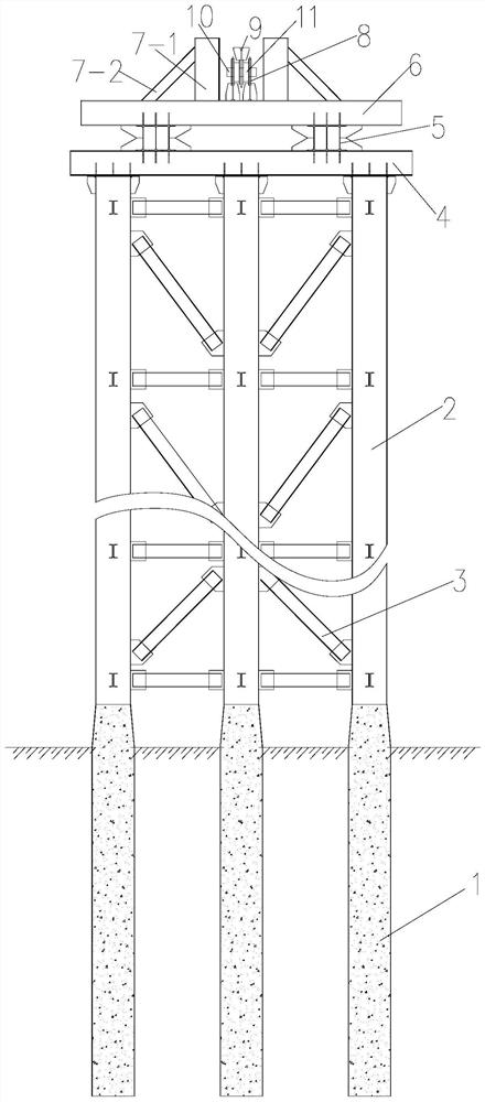
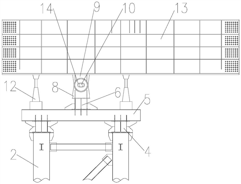
[0039] Such as Figure 1 to Figure 5As shown, a temporary pier support method for a long-span steel-concrete composite girder cable-stayed bridge of the present invention, the long-span steel-concrete composite Bridge, the method includes the following steps:

[0040] Step 1. Determine the location of temporary pier support: build a simulation model of a long-span steel-concrete composite girder cable-stayed bridge and conduct a wind-resistant performance test on the simulation model of a long-span steel-concrete composite girder cable-stayed bridge through a wind tunnel test of an equal-scale model , to obtain the support position interval of temporary piers at side spans under the improved wind resistance performance of the simulation model of long-span steel-concrete composite girder cable-stayed bridge;

[0041] Determine the best supporting position of temporary piers on side spans in combination with site topography, geological conditions, construction difficulty and co...


PUM


Abstract

The invention discloses a temporary pier support method for a long-span steel-concrete composite girder cable-stayed bridge, comprising the steps of: 1. determining the temporary pier support position; 2. setting boundary constraint conditions; 1. Determine the timing of temporary pier demolition; 5. Set up temporary pier. The present invention determines the optimal support position of the temporary pier on the side span through wind resistance performance detection, site topography, geological conditions, construction difficulty and construction safety, sets boundary constraint conditions, and determines the timing of temporary pier installation and temporary pier removal, so as to provide future Make full preparations for temporary pier support, by installing the upper support lug at the bottom of the steel girder, the upper support lug cooperates with the two lower support lugs installed on the transverse limit frame, the lower support lug and the upper support lug There are waist-shaped holes that match the supporting connectors on both sides, allowing the cable-stayed bridge to have a certain displacement change in the longitudinal direction, limiting the vertical displacement change of the steel main girder, and the force is clear.

Description

technical field [0001] The invention belongs to the technical field of temporary pier support, and in particular relates to a temporary pier support method for a long-span steel-concrete composite girder cable-stayed bridge. Background technique [0002] Temporary piers are temporary bridge piers erected for structural stress and safety during bridge construction. With the continuous development of bridge design and construction technology, more and more long-span steel-concrete composite girder cable-stayed bridges are being built. During the construction of long-span steel box girder cable-stayed bridges, temporary piers must be set up to ensure the safety and stability of the cable-stayed bridge before closing. However, the addition of temporary piers will cause significant changes in the deflection of the tower, which will increase the difficulty of controlling the alignment of the long-span steel-concrete composite girder cable-stayed bridge. Load, and affected by the ...

Claims


Application Information

Patent Timeline
Patent Type & Authority Patents(China)
IPC IPC(8): E01D21/00E01D19/02E01D11/04E01D101/30
CPCE01D11/04E01D19/02E01D21/00E01D2101/30
Inventor 魏家乐舒涛杨继承朱东方雷波涛张记众黄源
Owner 陕西交控通宇交通研究有限公司
Learn More