
Improved CFAR detection method

A detection method and detection unit technology, applied in the direction of radio wave measurement systems, instruments, etc., can solve the problems of reducing the radar detection distance, missed detection, and the radar cannot detect the target, so as to increase the radar detection distance and improve the detection probability.

Inactive Publication Date: 2020-07-10
XIAMEN UNIV
View PDF7 Cites 0 Cited by
  • Summary
  • Abstract
  • Description
  • Claims
  • Application Information

AI Technical Summary

Problems solved by technology

In this case, since the threshold factor value depends on the false alarm rate and has nothing to do with the distance, it will cause the radar to fail to detect the target, resulting in missed detection and reducing the detection range of the radar

Method used


Image

  • Improved CFAR detection method
  • Improved CFAR detection method
  • Improved CFAR detection method

Examples


Embodiment Construction

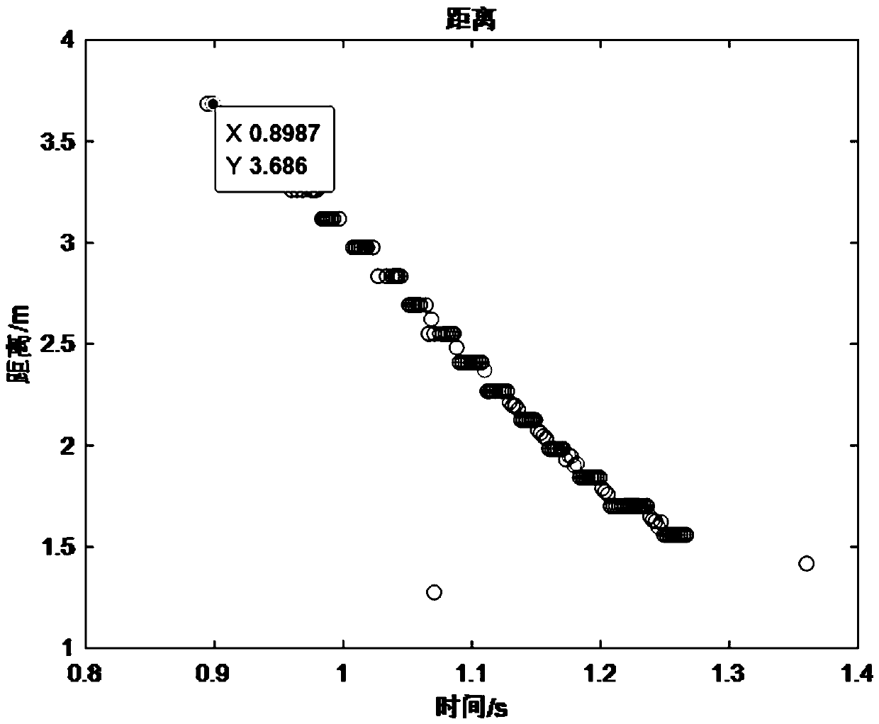
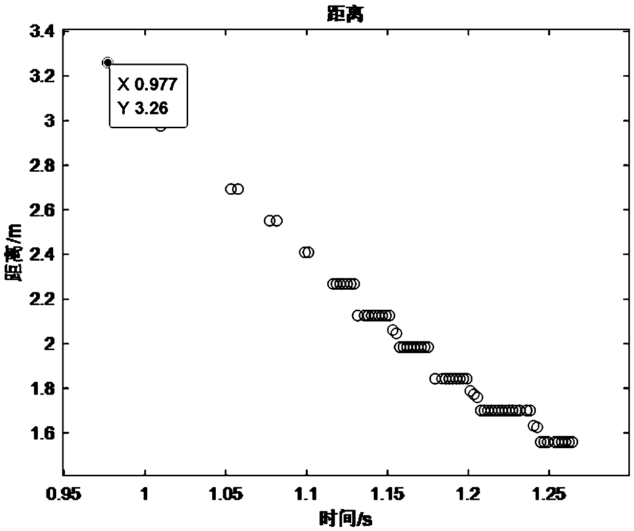
[0022] like figure 1 As shown, the present invention discloses an improved CFAR detection method. On the basis of CFAR, an additional distance factor is considered for the extraction of the threshold factor, so as to improve the target detection probability and increase the radar detection distance. The detection method is as follows:

[0023] Step 1. Input the detection signal, which is the target range image signal obtained by processing the radar echo signal. The abscissa is the distance dimension, and the ordinate is the amplitude.

[0024] Step 2. Perform the following processing on each detection unit of the detection signal:

[0025] Step 2.1. Estimate the distance factor for each detection unit to obtain the distance factor δ; wherein, the criterion for estimating the distance factor is: the larger the distance, the smaller the value of the distance factor.

[0026] Step 2.2, threshold calculation;

[0027] The threshold V of each detection unit is obtained by multi...


PUM


Abstract

The invention relates to an improved CFAR detection method, which considers the distance factor of radar target detection and increases the distance factor during threshold calculation, thereby improving the detection probability of a target and increasing the radar detection distance.

Description

technical field [0001] The invention relates to the technical field of radar detection, in particular to an improved CFAR detection method. Background technique [0002] Radar signal detection technology plays an important role in improving radar performance and enhancing target detection capabilities. Detection is the process of comparing a signal to a threshold. In a radar system, in order to reduce the cost caused by false detection, it is hoped that the detection threshold can not only maximize the detection probability, but also make the false alarm rate below a preset level. Therefore, in general the threshold is a function of the probability of detection and the probability of false alarm. In radar simulation, the signal noise is generally taken as Gaussian white noise, but in practical applications, the noise is often colored noise, and the power is unknown. [0003] CFAR (Constant False Alarm Rate Detection) technology can solve these problems. When detecting a g...

Claims


Application Information

Patent Timeline
IPC IPC(8): G01S7/40
CPCG01S7/4004
Inventor 张贻雄谢阳铭
Owner XIAMEN UNIV
Learn More