
Motor controller full-automatic testing device

A fully automatic testing and motor controller technology, applied in electrical testing/monitoring, program control, general control systems, etc., can solve problems such as low production efficiency, potential safety hazards, inability to meet actual production capacity, etc., to achieve convenient operation and ensure normal operation. Use and facilitate the effect of motor performance testing

Pending Publication Date: 2020-07-10
昆山迈征自动化科技有限公司
View PDF0 Cites 0 Cited by
  • Summary
  • Abstract
  • Description
  • Claims
  • Application Information

AI Technical Summary

Problems solved by technology

[0002] Before leaving the factory, the motor controller needs to be subjected to a performance simulation test. The specific test process is as follows: First, the motor controller is placed on the workbench manually, and the product is qualitatively positioned and clamped. After the product is clamped, the motor and the equipment are manually clamped. After the product docking is completed, the test is manually started to test the product. In the above performance test, the product needs to be manually moved, positioned, and docked, which is time-consuming and laborious, and the production efficiency is low, which cannot meet the actual production capacity; There are certain safety hazards in the docking method of locking screws, and there may be cases where the docking is not done well, which will affect the use of the equipment

Method used


Image

  • Motor controller full-automatic testing device
  • Motor controller full-automatic testing device
  • Motor controller full-automatic testing device

Examples


Embodiment Construction

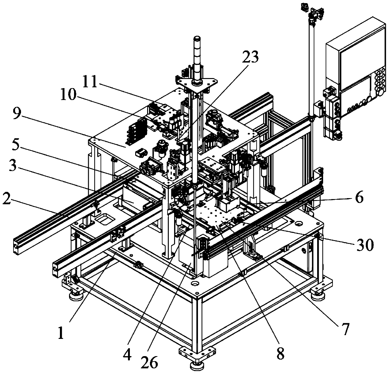
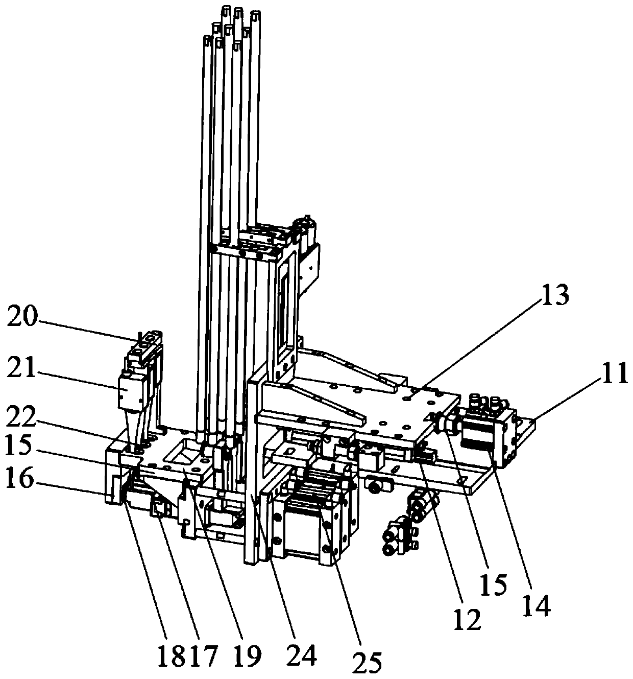
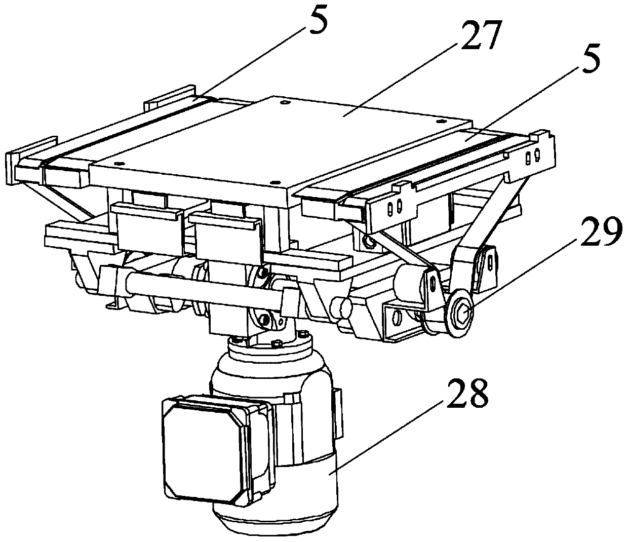
[0017] Such as Figure 1 ~ Figure 4 As shown, the present invention includes a frame 1, a streamline track 2 is arranged at one end of the frame 1, and a traverse mechanism 3 perpendicular to the direction of motion is provided at the streamline track 2, and the frame 1 is in addition One end is provided with conveyer 4, and described traversing mechanism 3 is identical with the moving direction of described conveyer 4, and described traversing mechanism 3 comprises traversing conveyer belt 5, and the conveyer belt 6 of described conveyer 4, traversing conveying The installation heights of the belt 5 and the streamline track 2 are consistent, and the frame 1 located at the conveyor 4 is provided with a jacking mechanism 8, and the jacking mechanism 8 includes a jacking plate 7, and the jacking plate 7 The lower part is connected with a jacking cylinder (not shown in the figure) mounted on the frame 1, a tooling seat 9 is arranged above the traverse mechanism 3, and a plug dock...


PUM


Abstract

The invention provides a motor controller full-automatic testing device which is convenient to operate, facilitates motor performance testing, saves time and labor and can guarantee normal use. A streamline track is arranged at one end of a rack. A transverse moving mechanism perpendicular to the moving direction of the streamline track is arranged at the streamline track. A conveyor is arranged at the other end of the rack, the transverse moving mechanism comprises a transverse moving conveying belt. A jacking mechanism is arranged on the rack positioned at the conveyor. The lower part of a jacking plate of the jacking mechanism is connected with a jacking cylinder. A tool seat is arranged above the transverse moving mechanism. A plug butt joint mechanism is assembled on the tool base. The plug butt joint mechanism comprises a fixed seat. Sliding rails are arranged on the fixing base, an L-shaped clamping base is installed on the sliding rail, a clamping air cylinder is arranged on the fixing base located on one side of the clamping base and connected with a first floating connector so as to make contact with the clamping base. A butt joint plate is installed at the bottom of thetool base located on the other side of the clamping base, a copper bar probe is installed on the lower portion of the clamping base, and an inserting opening is formed in the butt joint plate corresponding to the copper bar probe.

Description

technical field [0001] The invention relates to the technical field of motors, in particular to a fully automatic testing device for motor controllers. Background technique [0002] Before leaving the factory, the motor controller needs to be subjected to a performance simulation test. The specific test process is as follows: First, the motor controller is placed on the workbench manually, and the product is qualitatively positioned and clamped. After the product is clamped, the motor and the equipment are manually clamped. After the product docking is completed, the test is manually started to test the product. In the above performance test, the product needs to be manually moved, positioned, and docked, which is time-consuming and laborious, and the production efficiency is low. It cannot meet the actual production capacity; the docking adopts manual There are certain potential safety hazards in the docking method of locking screws, and there may be cases where the docking...

Claims


Application Information

Patent Timeline
IPC IPC(8): G05B23/02
CPCG05B23/0224G05B2219/24065
Inventor 吕光辉
Owner 昆山迈征自动化科技有限公司
Learn More