Enameled wire manufacturing and processing process

A processing technology, enameled wire technology, applied in cable/conductor manufacturing, transportation and packaging, and conductor/cable insulation, etc. Line operation, improve the efficiency of the line take-up, the effect of reducing the capacity of the line

Inactive Publication Date: 2020-07-10
盛珊瑜
View PDF0 Cites 3 Cited by
  • Summary
  • Abstract
  • Description
  • Claims
  • Application Information

AI Technical Summary

Problems solved by technology

[0003] However, the existing enameled wire has the following problems when it is rolled up. a. When the traditional enameled wire winding mechanism is used for winding up the enameled wire, the back turns of the wire are pressed against the front turns of the wire, and when it reaches a certain height, it suddenly collapses. The rear coil of wire is pressed under the front coil of wire, which affects the use, and it is often necessary to re-wind the wire, which is time-consuming and laborious; b. When the traditional enameled wire is wound, the first batch of wires and the second batch of wires often appear to be aligned. Cross shape, there are many gaps in the enameled wire on the wire reel, the wire capacity of the wire reel is reduced, and the appearance of the enameled wire is messy. Often due to excessive tension, the paint layer of the enameled wire may crack, deform, or even break. Take-up operation is carried out to improve the efficiency of enameled wire take-up

Method used


Image

  • Enameled wire manufacturing and processing process
  • Enameled wire manufacturing and processing process
  • Enameled wire manufacturing and processing process

Examples


Embodiment Construction

[0034] The embodiments of the present invention will be described in detail below with reference to the accompanying drawings, but the present invention can be implemented in many different ways defined and covered by the claims.

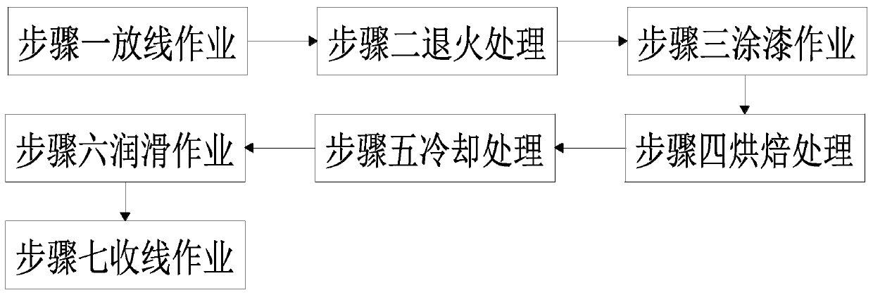
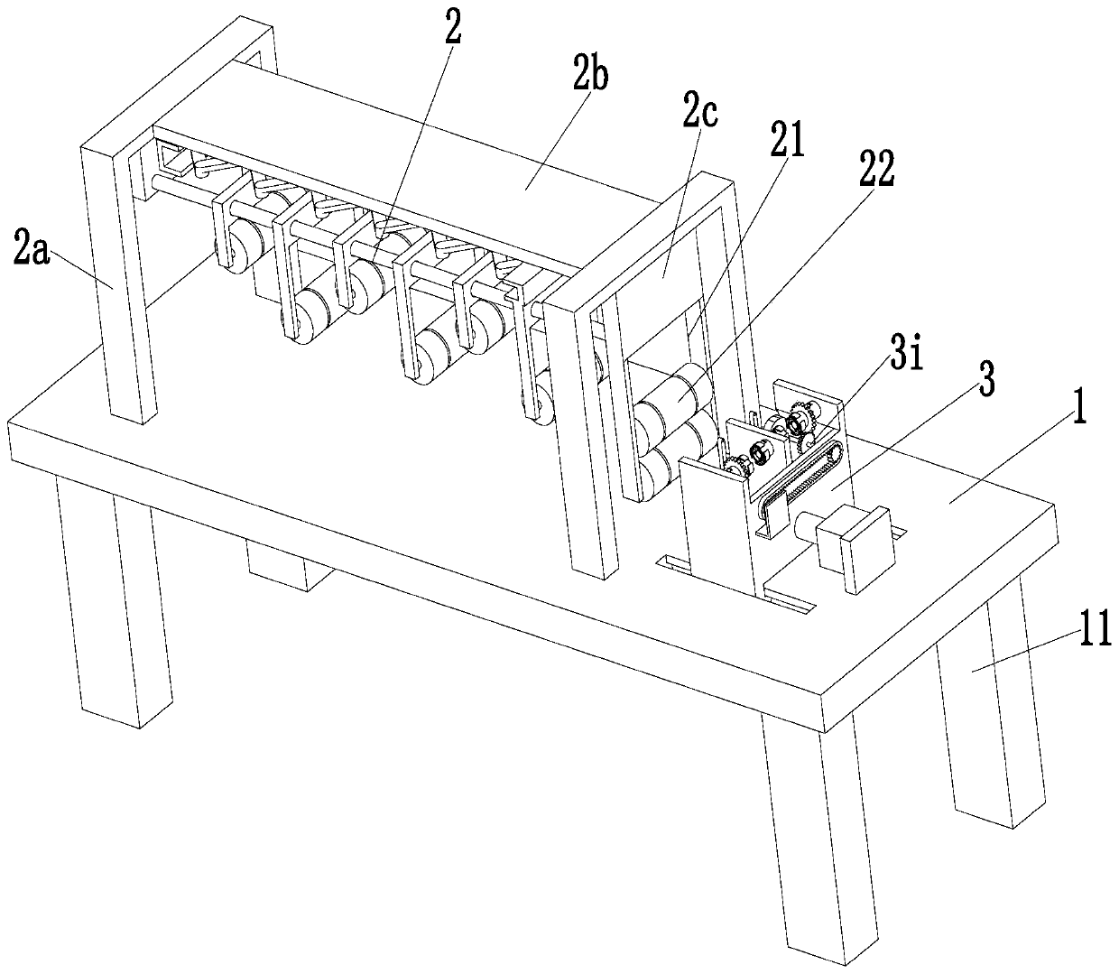
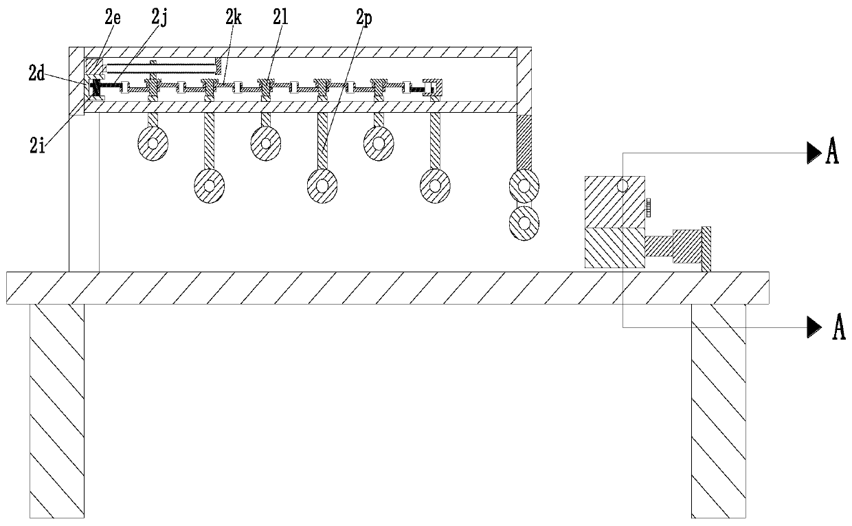
[0035] Such as Figure 1 to Figure 8 As shown, an enameled wire manufacturing process mainly includes the following steps:

[0036] Step 1, pay-off operation: manual pay-off operation on the wires, to obtain the wires that have been paid off;

[0037] Step 2, annealing treatment: performing annealing treatment on the drawn wire obtained in step 1, so that the wire is heated at a certain temperature to reach the softness required by the process, and an annealed wire is obtained;

[0038] Step 3, painting operation: apply enameled wire varnish to the annealed wire obtained in step 2 to form a uniform paint layer with a certain thickness, and obtain a painted wire;

[0039] Step 4, baking treatment: baking the painted wire obtained in step 3 to obtai...


PUM


Abstract

The invention relates to an enameled wire manufacturing and processing process. The process mainly comprises the following steps: paying-off operation, annealing treatment, painting operation, bakingtreatment, cooling treatment, lubricating operation, take-up operation and the like. The used enameled wire take-up equipment comprises a bottom plate, a stretching device and a take-up device. The provided process can solve the following problems existing in winding of existing enameled wires: a) when a traditional enameled wire winding mechanism is used for winding an enameled wire, several rearcircles of wires are pressed on several front circles of wires, the enameled wires collapse suddenly when reaching a certain height to make the rear circle of wires pressed under the front circle ofwires, so that use is affected, wire winding operation needs to be conducted again frequently, and time and labor are wasted; and b) when the traditional enameled wires are wound, the first batch of wires and the second batch of wires are often arranged in a crossed shape, gaps of the enameled wires on a wire disc are large, the wire capacity of the wire disc is reduced, and the enameled wires aredisordered in appearance.

Description

technical field [0001] The invention relates to the technical field of enameled wire manufacturing and processing, in particular to an enameled wire manufacturing and processing technology. Background technique [0002] Enameled wire is a main variety of winding wire, which is composed of conductor and insulating layer. After the bare wire is annealed and softened, it is painted and baked many times. Enameled wire is widely used in motors, electrical appliances and household appliances. Especially in recent years, the power industry has achieved sustained and rapid growth, and the rapid development of household appliances has brought a wider field of application of enameled wire. After the enameled wire is produced, it must be wound on a reel for subsequent storage and transportation. and sales. [0003] However, the existing enameled wire has the following problems when it is rolled up. a. When the traditional enameled wire winding mechanism is used for winding up the enam...

Claims


Application Information

Patent Timeline
Patent Type & Authority Applications(China)
IPC IPC(8): H01B13/16B65H54/28
CPCB65H54/2818B65H54/2848H01B13/165
Inventor 盛珊瑜吕宁
Owner 盛珊瑜
Why Eureka
Try Eureka