Electric wire pliers for aerial work

A high-altitude operation and wire technology, applied in the installation of pliers, electrical components, cables, etc., can solve the problems of the influence of the conductive efficiency of the rubber insulated wire and the fracture of the inner core.

Active Publication Date: 2020-12-22
JIANGSU ELECTRIC POWER CO
View PDF9 Cites 0 Cited by
  • Summary
  • Abstract
  • Description
  • Claims
  • Application Information

AI Technical Summary

Problems solved by technology

[0003] Since the inner core of the multi-strand rubber insulated wire is composed of multiple thinner copper wires, and the outer rubber insulation is so tough that the electric wire pliers for aerial work need to pull repeatedly on the surface when peeling it, resulting in The inner core of the multi-strand rubber insulated wire is prone to partial fracture during pulling, which affects the conductive efficiency of the multi-strand rubber insulated wire

Method used


Image

  • Electric wire pliers for aerial work
  • Electric wire pliers for aerial work
  • Electric wire pliers for aerial work

Examples


Embodiment 1

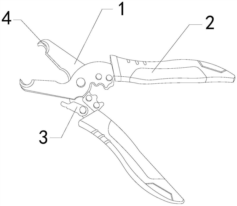
[0027] For example figure 1 -example Figure 5 Shown:

[0028] The invention provides a wire pliers for high-altitude operation, the structure of which includes a jaw 1, a handle 2, a limit block 3, and a circumcision mechanism 4. The jaw 1 and the handle 2 are embedded and connected, and the limit block 3 Engaging with the pliers mouth 1 movably, the circumcision mechanism 4 and the pliers mouth 1 are an integrated structure.

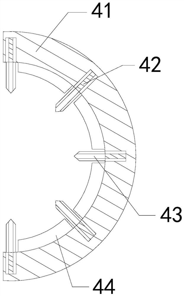
[0029] Wherein, the circumcision mechanism 4 includes an outer frame 41, a housing groove 42, a peeling mechanism 43, and a fixing block 44, the housing groove 42 and the outer frame 41 are an integrated structure, and the peeling mechanism 43 is installed in the housing groove 42. At the front end position, the fixed block 44 is embedded in the left surface position of the outer frame 41, and the inside of the accommodating groove 42 is hollowed out on both sides, so that the solid block in the middle can be connected with the peeling mechanism 43, ...

Embodiment 2

[0036] For example Figure 6 -example Figure 8 Shown:

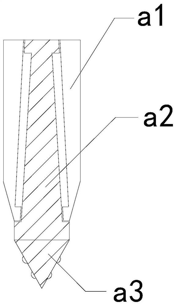
[0037] Wherein, the piercing head a3 includes a housing a31 and a cutting ring a32, the cutting ring a32 is movably engaged with the housing a31. The left and right sides of the housing are symmetrically distributed, which is beneficial for the shell a31 to pierce the rubber insulation on the wire.

[0038]Wherein, the cutting ring a32 includes a cut-off piece c1, a joint ring c2, and a central axis c3, the cut-off piece c1 is embedded and connected to the joint ring c2, and the inner surface of the joint ring c2 is attached to the outer surface of the central axis c3 , the cut-off piece c1 is provided with sixteen pieces, and is evenly distributed in a circular shape on the outer surface of the joint ring c2. When the cut-off piece c1 is pushed upward by the rubber insulation, the joint ring c2 can be moved along the central axis c3 Rotate, so that the rotating cutting piece c1 can continuously cut the rubber insulat...


PUM


Abstract

The invention discloses a wire clamp for aloft work. The wire clamp structurally comprises a clamp mouth, grips, a limiting block and a ring-cutting mechanism. The clamp mouth is fixedly connected with the grips in an embedded manner. The limiting block is movably clamped to the clamp mouth. The ring-cutting mechanism and the clamp mouth are of an integrated structure. The outer skin of a multi-strand rubber insulated wire can penetrate through an accommodating groove in the ring cutting mechanism, a worker slightly swings the grips, therefore, a sliding block on a peeling mechanism can carryout ring cutting on the rubber insulation skin, and the situation in which the inner core is easy to partially break in the pulling process due to repeated pulling during peeling of the multi-strand rubber insulated wires is avoided. A cutting ring on a piercing head can be matched with a shell to peel the aged and hardened rubber insulation skin, and a cutting piece on the cutting ring can cut the aged rubber insulation skin through extrusion force generated on the cutting ring when the shell pierces into the aged rubber insulation skin.

Description

technical field [0001] The invention relates to the field of high-altitude operations, in particular to an electric wire pliers for high-altitude operations. Background technique [0002] Wire pliers for high-altitude work are mainly used for cutting and peeling high-altitude wires. By manually pressing the handle, the top jaw can cut and peel the wires. It is widely used in electric power construction and other industries. Based on the above description The inventors found that the existing a kind of high-altitude electric wire pliers mainly has the following deficiencies, for example: [0003] Since the inner core of the multi-strand rubber insulated wire is composed of multiple thinner copper wires, and the outer rubber insulation is so tough that the electric wire pliers for aerial work need to pull repeatedly on the surface when peeling it, resulting in The inner core of the multi-strand rubber insulated wire is prone to partial fracture during pulling, thereby affecti...

Claims


Application Information

Patent Timeline
Patent Type & Authority Patents(China)
IPC IPC(8): H02G1/12B25B7/00B25B7/22
CPCB25B7/00B25B7/22H02G1/1209
Inventor 白海山
Owner JIANGSU ELECTRIC POWER CO
Why Eureka
Try Eureka