
side channel blower

A technology of blower and side channel, which is applied in the field of side channel blower, can solve the problems of low efficiency and achieve the effect of increasing flux

Active Publication Date: 2022-04-29
PIERBURG GMBH & CO KG NEUSS
View PDF11 Cites 0 Cited by
  • Summary
  • Abstract
  • Description
  • Claims
  • Application Information

AI Technical Summary

Problems solved by technology

However, it turned out that although the pressure shock could be reduced and the noise emission correspondingly reduced, the efficiency was still too low

Method used


Image

  • side channel blower
  • side channel blower
  • side channel blower

Examples


Embodiment Construction

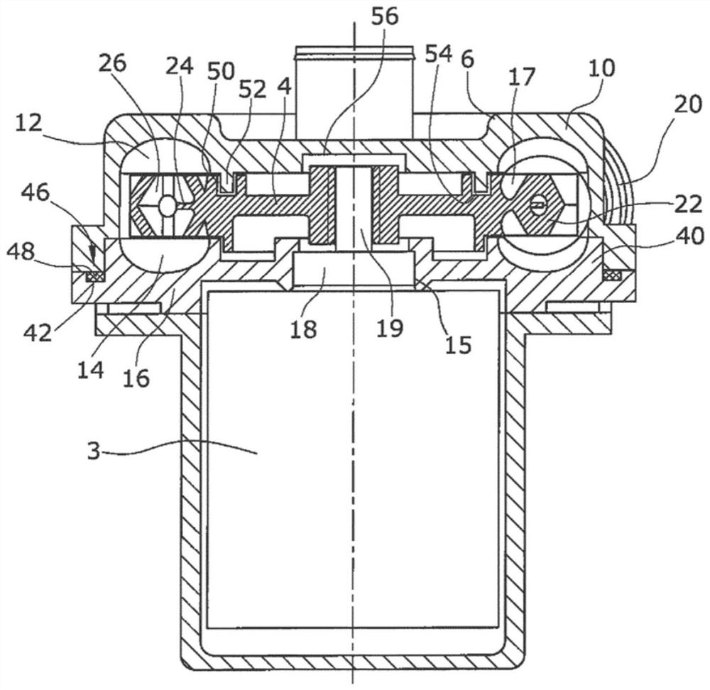
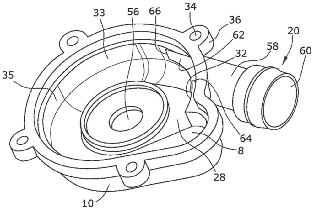
[0017] in the attached figure 1 The side-channel blower shown in FIG. 2 consists of a two-part housing 2 and an impeller 4 , for example for conveying air, which is rotatably mounted in the housing 2 and driven by a drive unit 3 . The air reaches the inlet region 8 of the first housing part 10 through the axial inlet 6 (see figure 2 ), the first housing part is used in this embodiment as the tank part of the side channel blower. From the inlet area 8, the air then flows into two substantially annularly extending delivery channels 12, 14, wherein the first delivery channel 12 is formed in the cover part 10 and the second delivery channel 14 is formed in the second housing part 16, at In this embodiment, the second housing part 16 serves as the cover part of the side channel blower. Thus, the tank part 10 and the cover part 16 enclose a blower chamber 17 .

[0018] The cover part 16 has a central opening 15 , in which a bearing 18 of a drive shaft 19 of the drive unit 3 is a...


PUM


Abstract

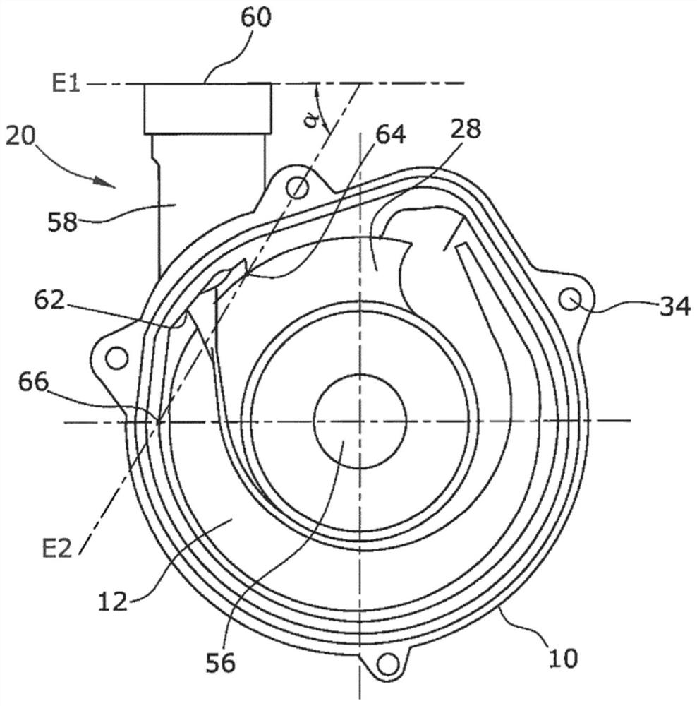
Side-channel blowers with devices for minimizing noise emissions are known, however, they are often insufficient and limit the volume flow to be conveyed or have low efficiency. Therefore, the present invention proposes a side channel blower in which the first side edge (64) and the second side edge (66) form a first plane E 1 , the first plane E 1 and the second plane E spanned by the outlet (60) 2 At an angle α≧30°, the outlet opening ( 62 ) protrudes into the radial boundary wall ( 33 ) in this way. With such an embodiment, the efficiency and the maximum volume flow to be delivered can be significantly increased.

Description

technical field [0001] The invention relates to a side channel blower, in particular a secondary blower for an internal combustion engine, which has a multipart housing with at least a first housing part and a second housing part, the first The housing part is designed as a tank part, and the second housing part is designed as a cover part, wherein the tank part and the cover part are connected to each other in the interface via an interposed sealing element and enclose a blower chamber, wherein , formed with an inlet and an outlet, the inlet leads to at least one substantially annularly extending conveying channel with a radial boundary wall via the inlet region, the side channel blower has an impeller, which can be driven by a drive unit to be rotatable installed in the housing in a manner, and has conveying blades cooperating with the opposite conveying channels, and the side channel blower has an interrupted area between the inlet and the outlet, in which at least one conv...

Claims


Application Information

Patent Timeline
Patent Type & Authority Patents(China)
IPC IPC(8): F04D23/00F04D29/08F04D29/42
CPCF04D23/008F04D29/083F04D29/4226
Inventor 亚历山大·高特托马斯·约斯根佩特拉·戴特阿尔佩·卡潘科瑞山·范德比克马蒂亚斯·布托罗斯-米哈伊尔
Owner PIERBURG GMBH & CO KG NEUSS
Learn More