A floating device and method

A technology of mounting parts and movable flanges, applied in the field of automation, can solve the problems of high cost, affecting the processing range, occupying the processing space of the machine tool, etc., to achieve the effects of improving stability, improving load utilization, and easy maintenance

Active Publication Date: 2022-01-18
YASKAWA SHOUGANG ROBOT CO LTD
View PDF6 Cites 0 Cited by
  • Summary
  • Abstract
  • Description
  • Claims
  • Application Information

AI Technical Summary

Problems solved by technology

This solution requires additional investment in positioning tooling, which is expensive, and the tooling will occupy the processing space of the machine tool and affect the processing range

Method used


Image

  • A floating device and method
  • A floating device and method
  • A floating device and method

Examples


Embodiment Construction

[0038] The preferred embodiments of the present invention will be described below in conjunction with the accompanying drawings. It should be understood that the preferred embodiments described here are only used to illustrate and explain the present invention, and are not intended to limit the present invention.

[0039] Explanation of related terms

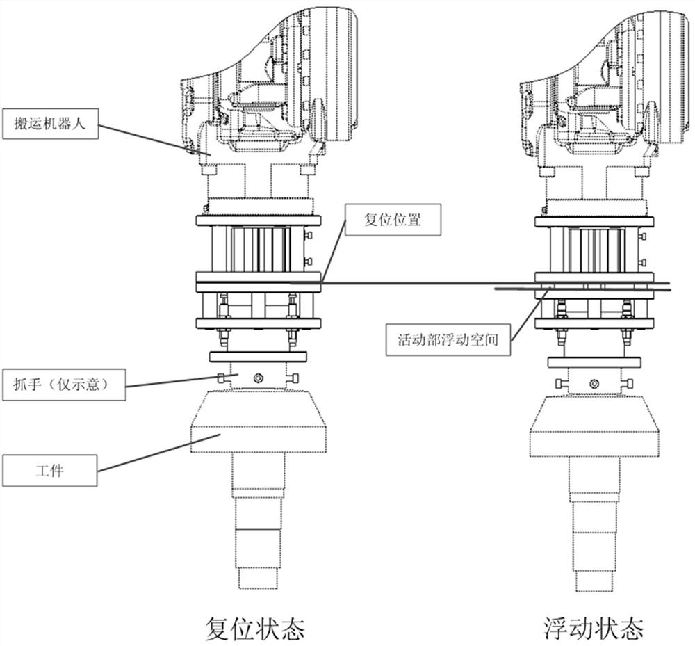
[0040] Robot gripper: An actuator installed on the front end of a multi-joint robot or a Cartesian robot to grab a workpiece.

[0041] Hydraulic buffer: a safety buffer device that uses hydraulic damping to decelerate objects acting on it until it stops, preventing hard collisions.

[0042] Centering function: connect two or more rotating bodies and make their axis lines on the same line.

[0043] Reset function: After one or more objects have changed their positions and postures, restore them to their original positions and postures.

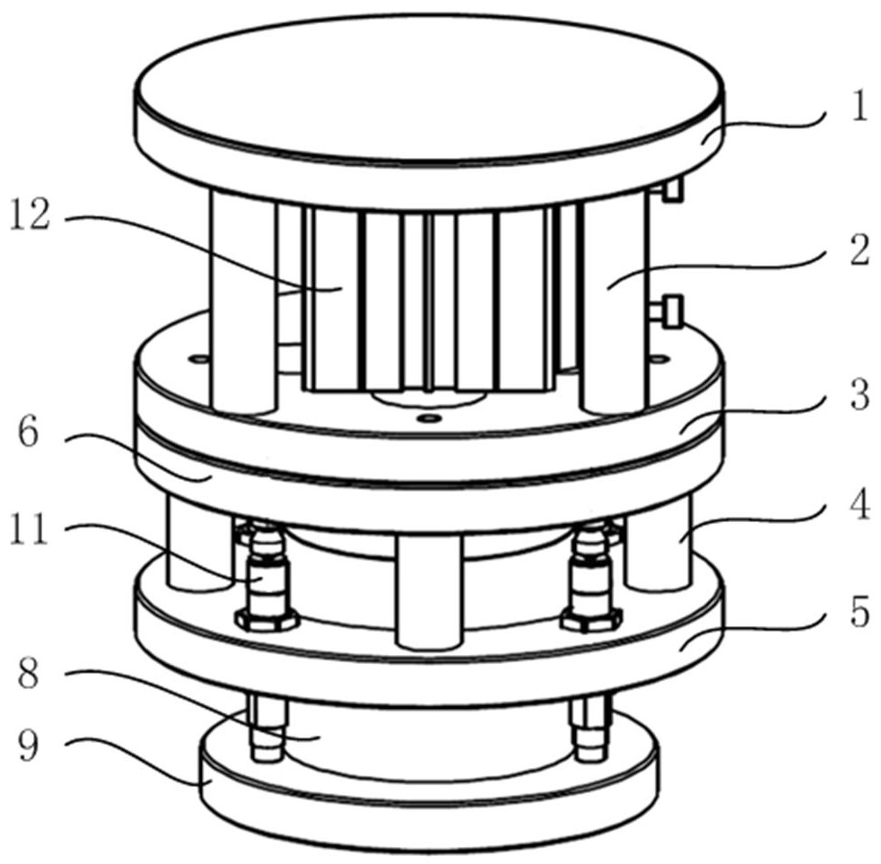
[0044] figure 1 It is a schematic diagram of the three-dimensional structure of the floati...


PUM


Abstract

A floating mounting device, comprising a fixed frame, a movable part, a floating function part and a reset function part, wherein the movable part is sleeved on the fixed frame, and driven by the reset function part along the The fixed frame moves up and down; the floating function part is fixed on the fixed frame to support the movable part; the reset function part is fixed on the fixed frame to drive the movable part to reset. The invention also provides a floating loading method, which provides a soft sliding action, simulates the manual loading process, effectively replaces manual work, and reduces costs.

Description

technical field [0001] The invention relates to the technical field of automation, in particular to a floating loading device and method. Background technique [0002] In the prior art, when the tooth surface of the contour bevel gear is processed by a dry milling machine, it is usually necessary to rely on the worker to cooperate and install the tail cone of the blank to be processed with the taper sleeve of the machine tool spindle, because the gap between the taper sleeve of the machine tool spindle and the blank The matching precision is high, and the current technology is mostly installed manually by feeling, and the installation process needs to be pressed while shaking, which is an assembly process that relies on experience. [0003] In order to reduce the labor intensity of workers, it is necessary to use robots instead of workers to install blank parts. In the automation transformation of robots replacing workers, if only the robot is used to drive the rigid grippe...

Claims


Application Information

Patent Timeline
Patent Type & Authority Patents(China)
IPC IPC(8): B23F23/04B23F23/00B23Q7/04
CPCB23F23/04B23Q7/04
Inventor 马永李晓燕高宏伟
Owner YASKAWA SHOUGANG ROBOT CO LTD
Why Eureka
Try Eureka