Shock absorption device of electromechanical equipment

A technology of shock absorbing device and electromechanical equipment, applied in mechanical equipment, springs/shock absorbers, supporting machines, etc., can solve the problems of noise pollution, large vibration amplitude, large noise, etc., to extend service life, reduce vibration intensity, The effect of reducing the vibration intensity

Inactive Publication Date: 2020-07-14
潘科峰
View PDF11 Cites 11 Cited by
  • Summary
  • Abstract
  • Description
  • Claims
  • Application Information

AI Technical Summary

Problems solved by technology

[0003] When the electromechanical equipment is working, it will vibrate slightly. If the vibration is not effectively damped, the service life of the electromechanical equipment will be severely shortened, and serious noise pollution will also be caused. However, the existing shock absorber device for electromechanical equipment is not convenient for installing and fixing the electromechanical equipment. , can not improve the stability of the electromechanical equipment, so that the electromechanical equipment will produce a large vibration amplitude during the working process, which will not only generate large noise, but also affect the service life of the electromechanical equipment

Method used


Image

  • Shock absorption device of electromechanical equipment
  • Shock absorption device of electromechanical equipment
  • Shock absorption device of electromechanical equipment

Examples


Embodiment Construction

[0018] The following will clearly and completely describe the technical solutions in the embodiments of the present invention with reference to the accompanying drawings in the embodiments of the present invention. Obviously, the described embodiments are only some, not all, embodiments of the present invention. Based on the embodiments of the present invention, all other embodiments obtained by persons of ordinary skill in the art without making creative efforts belong to the protection scope of the present invention.

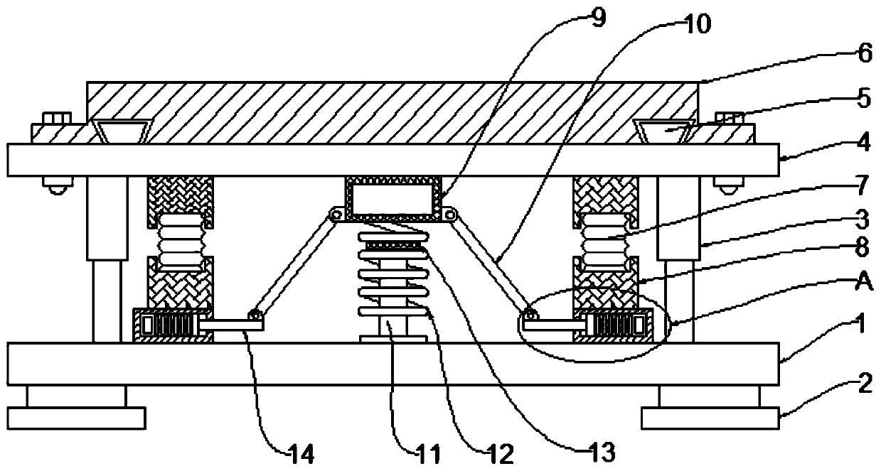
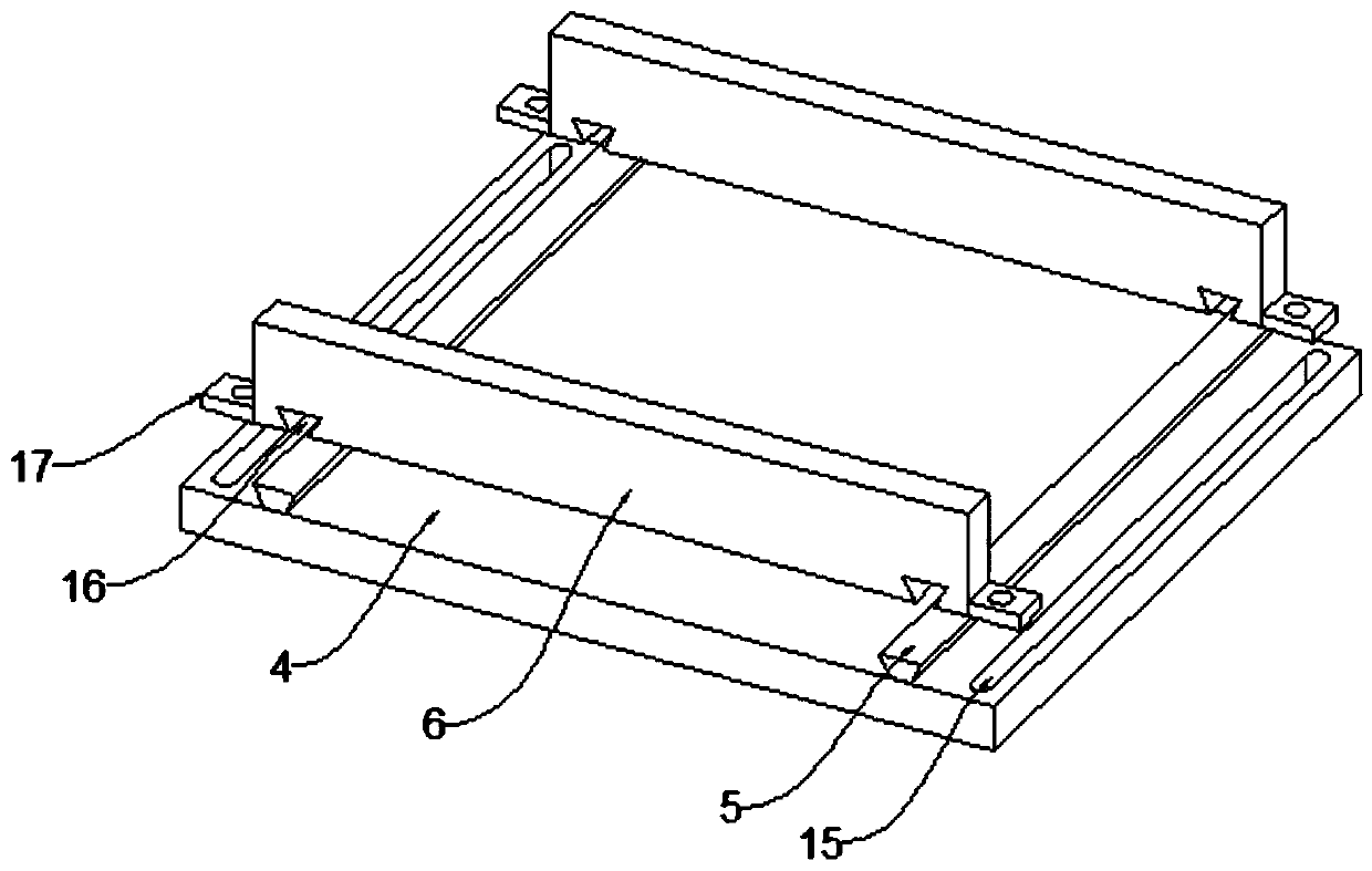
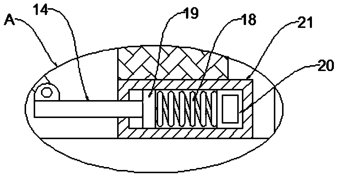
[0019] see Figure 1~3 , in an embodiment of the present invention, a shock absorbing device for electromechanical equipment, comprising a base 1, support pads 2 are provided at the four corners of the bottom of the base 1, telescopic rods 3 are provided on both sides of the upper surface of the base 1, the The top of the telescopic rod 3 is provided with a mounting plate 4, the two sides of the upper surface of the mounting plate 4 are movably connected with ...


PUM


Abstract

The invention discloses a shock absorption device of electromechanical equipment. The shock absorption device comprises a base. Supporting pads are arranged at the four corners of the bottom of the base. Telescopic rods are arranged on the two sides of the upper surface of the base. A mounting plate is arranged at the top ends of the telescopic rods. The two sides of the upper surface of the mounting plate are movably connected with limiting plates. A connecting plate is arranged at the middle position of the bottom of the mounting plate. The two sides of the connecting plate are rotationallyconnected with connecting rods through rotating shafts. The bottoms of the connecting rods are rotationally connected with moving rods through the rotating shafts. According to the shock absorption device, through cooperation between the mounting plate and the limiting plates, the shock absorption device can achieve adjusting conveniently according to the size of the bottom of the electromechanical equipment, and therefore the device is suitable for mounting of different sizes of electromechanical equipment; and through cooperation between arranged fixed bocks and kidney-shaped holes, the limiting plates can be fixed conveniently, and therefore the electromechanical equipment is fixed firmly, the electromechanical equipment is prevented from greatly shaking in the work process, and the stability of the electromechanical equipment is improved.

Description

technical field [0001] The invention relates to the field of electromechanical equipment, in particular to a vibration damping device for electromechanical equipment. Background technique [0002] Electromechanical equipment generally refers to machinery, electrical appliances, and electrical automation equipment. In construction, it refers to the general term for machinery and pipeline equipment other than geotechnical, carpentry, steel bars, and muddy water. It is different from hardware and mostly refers to finished products that can achieve certain functions. [0003] When the electromechanical equipment is working, it will vibrate slightly. If the vibration is not effectively damped, the service life of the electromechanical equipment will be severely shortened, and serious noise pollution will also be caused. However, the existing shock absorber device for electromechanical equipment is not convenient for installing and fixing the electromechanical equipment. , can no...

Claims


Application Information

Patent Timeline
Patent Type & Authority Applications(China)
IPC IPC(8): F16F15/08F16F15/02F16M11/04F16M11/26F16M7/00
CPCF16F15/085F16F15/02F16F15/03F16M11/04F16M11/26F16M7/00
Inventor 潘科峰陈婷项建微刘辉
Owner 潘科峰
Why Eureka
Try Eureka