Mandrel structure of spiral pusher of horizontal decanter centrifuge

A screw pusher and mandrel structure technology, which is applied to centrifuges, centrifuges with rotating drums, etc., can solve the problem of increasing the operating load and vibration intensity of the centrifuge, eccentric force generated by the screw pusher, and affecting equipment Service life and other issues, to achieve the effect of prolonging the service life of equipment, improving rigidity and simple structure

Pending Publication Date: 2020-07-17
CSSC NANJING LUZHOU MACHINE
View PDF0 Cites 3 Cited by
  • Summary
  • Abstract
  • Description
  • Claims
  • Application Information

AI Technical Summary

Problems solved by technology

Among them, the feeding method adopts the small end of the screw pusher to feed. This method can reduce the length of the feeding pipe and avoid the breakage of the feeding pipe, but it will cause part of the material to flow back into the outer side of the distributor and the spindle of the screw pusher. A large amount of material accumulates in the space between them, which causes the seal failure of the small end bearing of the screw propeller and causes the bearing to be damaged after entering the material; at the same time, the accumulated large amount of material will cause the screw propeller to generate eccentric force, increasing the operating load and vibration of the centrifuge Intensity, affecting the service life of equipment

Method used


Image

  • Mandrel structure of spiral pusher of horizontal decanter centrifuge
  • Mandrel structure of spiral pusher of horizontal decanter centrifuge

Examples


Embodiment Construction

[0015] Below in conjunction with accompanying drawing, technical scheme of the present invention is described in further detail:

[0016] The invention provides a novel mandrel structure of a screw pusher.

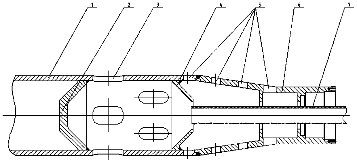
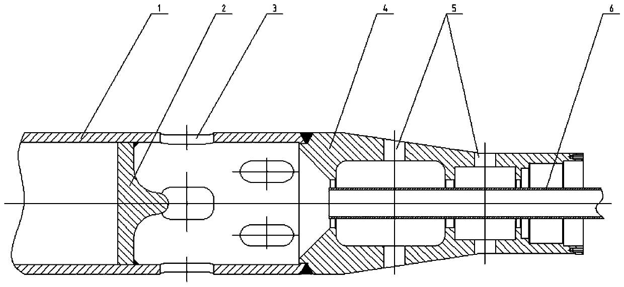
[0017] Such as figure 1 , when the material with a certain flow rate enters the distributing bin from the feed pipe 7, the distributing bin is formed by a combination of a column helix 1, a partition 2, and a cone plate 4, and most of the material enters the inner wall of the drum from the outlet 3 for separation, and a small part Due to the rebound of the partition 2, it will enter the conical helix 6 countercurrently, and most of it will enter the drum from the outlet 5. Since the outlet 5 is only four evenly distributed on the circumference, some materials will still accumulate in the cone after long-term use. In the accumulation space formed by the outside of the plate 4 and the conical helix 6, the screw pusher will generate eccentric force. In addition, due to the e...


PUM


Abstract

The invention discloses a mandrel structure of a spiral pusher of a horizontal decanter centrifuge. The mandrel structure is composed of a cylindrical spiral body, a conical spiral body and a partition plate, the spiral pusher is divided into a large end and a small end according to the size of the outer diameter of the spiral pusher, a feeding pipe enters a material distribution bin from the small end of the spiral pusher, the material distribution bin is an inner cavity formed by the conical spiral body, the cylindrical spiral body and the partition plate of the spiral pusher, the conical spiral body, the cylindrical spiral body and the partition plate are sequentially connected in the feeding direction of materials, the partition plate is arranged in the circumferential direction of theinner wall of the cylindrical spiral body, the partition plate is provided with a protrusion capable of rebounding materials and preventing the materials from reversely flowing into the conical spiral body in direction facing the feeding pipe, a first outlet which communicates with the material distribution bin is formed in circumference of the cylindrical spiral body, and the large end of conical spiral body adopts a conical surface structure. According to the mandrel structure of the spiral pusher of the horizontal decanter centrifuge, the rigidity of a spiral mandrel is improved, the reverse flow of the materials is reduced, a small amount of the reverse flow materials can be discharged in time, the operation load and the vibration intensity of the centrifuge are reduced, and the service life of the centrifuge is prolonged.

Description

technical field [0001] The invention relates to a mandrel structure of a screw pusher of a horizontal screw machine, specifically a novel mandrel structure, belonging to the technical field of engineering machinery. Background technique [0002] Decanter centrifuge is a horizontal spiral unloading, continuous operation settling equipment. Its working principle is that the drum and the screw feeder rotate at a high speed in the same direction with a certain difference in speed. The material is continuously introduced into the distribution bin of the screw feeder from the feed pipe, and enters the drum after being accelerated. Under the action of centrifugal force, the heavier The solid matter deposits on the drum wall to form a sediment layer, and the screw pusher continuously pushes the deposited solid phase matter to the cone end of the drum, and pushes it out of the machine through the slag outlet. Among them, the feeding method adopts the small end of the screw pusher to...

Claims


Application Information

Patent Timeline
Patent Type & Authority Applications(China)
IPC IPC(8): B04B1/20
CPCB04B1/20B04B2001/2041
Inventor 杨超高建生王存林卢仁伟朱兆帅陈鑫
Owner CSSC NANJING LUZHOU MACHINE
Why Eureka
Try Eureka