
Plastic product processing device

A technology for processing devices and plastic products, applied in the direction of manufacturing tools, grinding machines, grinding machine parts, etc., can solve the problems of inability to meet the needs of grinding, plastic deformation, etc., to achieve high accuracy, easy operation, and prevent the force from being too light. or overweight effect

Inactive Publication Date: 2020-07-17
邵东县乾兴塑料制品有限公司
View PDF9 Cites 2 Cited by
  • Summary
  • Abstract
  • Description
  • Claims
  • Application Information

AI Technical Summary

Problems solved by technology

[0002] After the molding of the plastic product is completed, the outer surface will have burrs, which need to be polished. The inventors found that in the prior art, the clamping structure cannot be well adapted to plastic products of different shapes and textures, resulting in During the clamping process, the plastic is deformed, and because the plastic products involve a wide range of fields and the shapes of the plastic products are different, the grinding structure in the prior art can no longer meet the actual grinding needs.

Method used


Image

  • Plastic product processing device
  • Plastic product processing device
  • Plastic product processing device

Examples


specific Embodiment approach 1

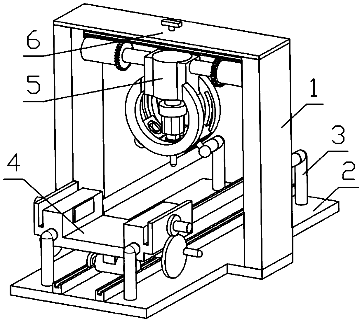
[0038] Combine below Figure 1-13 Describe this embodiment, a plastic product processing device, including a side support frame 1, a bottom mounting plate 2 and a rail rod 3, the rail rod 3 is fixedly installed on the bottom mounting plate 2, and the side support frame 1 is fixedly mounted on the bottom mounting plate 2 Above, the fixed mechanism 4 is slidably installed on the track rod 3, the fixed mechanism 4 is engaged with the bottom mounting plate 2, the multi-functional grinding mechanism 5 is fixedly installed on the angle adjustment mechanism 6, and the angle adjustment mechanism 6 is fixedly installed on the side support Rack 1.

specific Embodiment approach 2

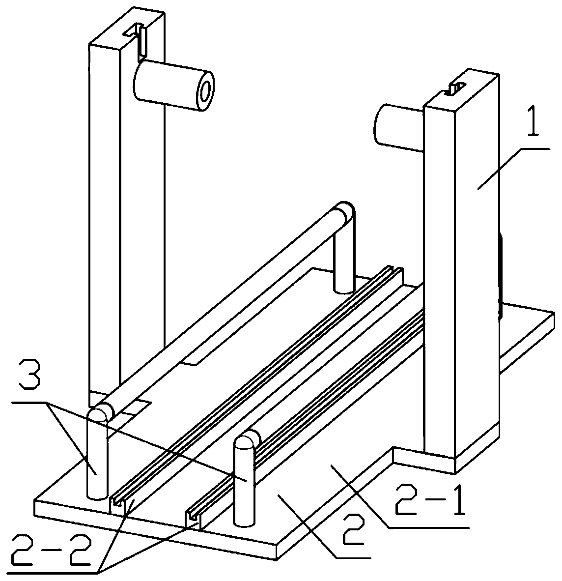
[0040] Combine below Figure 1-13 This embodiment will be described. This embodiment will further describe Embodiment 1. The bottom mounting plate 2 includes a main board 2-1 and a toothed track 2-2, and the main board 2-1 is fixedly connected to the toothed track 2-2.

specific Embodiment approach 3

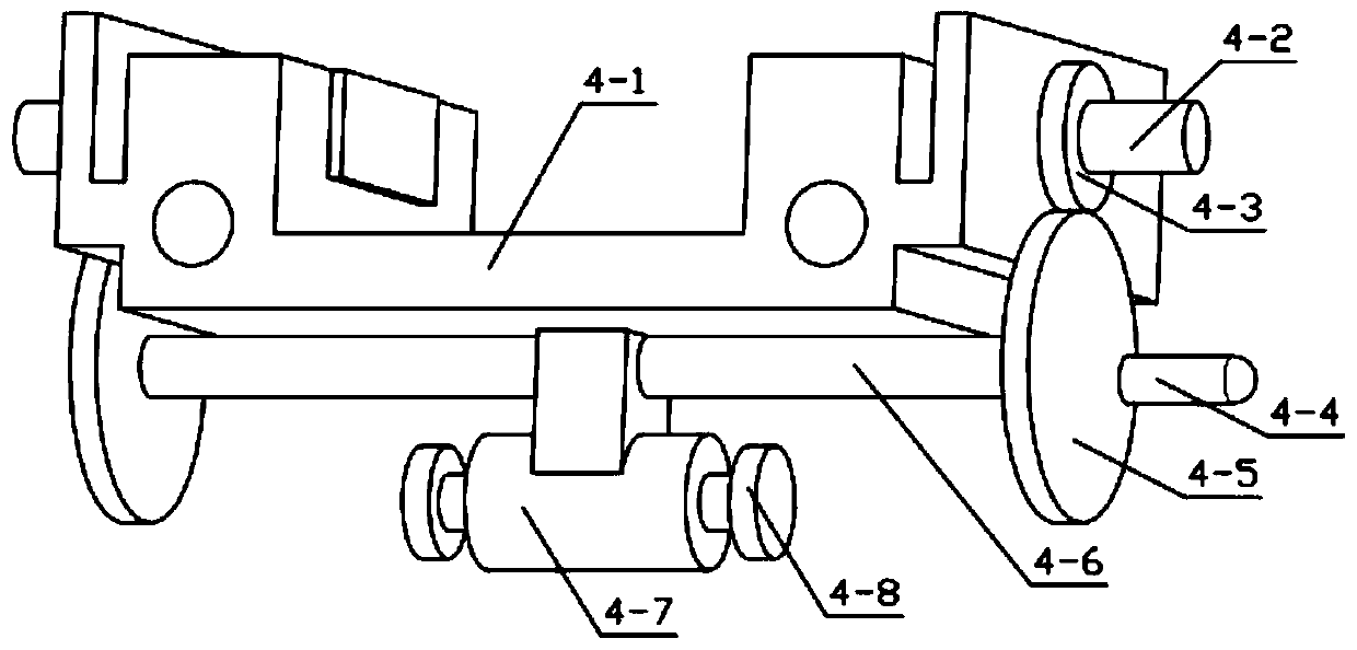
[0042] Combine below Figure 1-13 Describe this embodiment, this embodiment will further explain the second embodiment, the fixed mechanism 4 includes a U-shaped base 4-1, a threaded clamp block 4-2, an internal thread ring gear 4-3, a handle 4- 4. Main gear 4-5, connecting shaft 4-6, moving motor 4-7, displacement gear 4-8, threaded clamp block 4-2 is slidably installed on the through hole provided on U-shaped base 4-1, The U-shaped base 4-1 is slidably installed on the track rod 3, the internal thread ring gear 4-3 is rotatably installed on the U-shaped base 4-1, and the threaded clamp block 4-2 is threadedly connected with the internal thread ring gear 4-3, The internal thread ring gear 4-3 meshes with the main gear 4-5, the main gear 4-5 is fixedly connected with the handle 4-4, the main gear 4-5 is fixedly installed on the connecting shaft 4-6, and the connecting shaft 4-6 The rotation is installed on the U-shaped base 4-1, the mobile motor 4-7 is fixedly installed on the ...


PUM


Abstract

The invention relates to a plastic processing device, in particular to a plastic product processing device. The plastic product processing device comprises a side support frame, a bottom mounting plate and a track rod, wherein the track rod is fixedly installed on the bottom mounting plate, the side support frame is fixedly installed on the bottom mounting plate, a fixed mechanism is installed onthe track rod in a sliding mode, the fixed mechanism is engaged with the bottom mounting plate, a multifunctional grinding mechanism is fixedly installed on an angle adjusting mechanism, and the angleadjusting mechanism is fixedly installed on the side support frame. The device can be fixed completely according to plastic products of different properties, deformation cannot be generated, the plastic products can be ground at multiple angles by the device, so that the purpose of adaptation to different shapes is achieved, and grinding tools of the device can be freely replaced, so that different grinding requirements are met.

Description

technical field [0001] The invention relates to a plastic processing device, in particular to a plastic product processing device. Background technique [0002] After the molding of the plastic product is completed, the outer surface will have burrs, which need to be polished. The inventors found that in the prior art, the clamping structure cannot be well adapted to plastic products of different shapes and textures, resulting in During the clamping process, the plastic is deformed, and because the plastic products involve a wide range of fields and the shapes of the plastic products are different, the grinding structure in the prior art can no longer meet the actual grinding needs. Contents of the invention [0003] The main technical problem to be solved by the present invention is to provide a plastic product processing device, which can completely fix plastic products of different properties without deformation, and the device can grind plastic products from multiple a...

Claims


Application Information

Patent Timeline
Patent Type & Authority Applications(China)
IPC IPC(8): B24B9/20B24B41/06B24B41/00B24B41/02
CPCB24B9/20B24B41/002B24B41/02B24B41/06
Inventor 李春辉
Owner 邵东县乾兴塑料制品有限公司
Learn More