
Fixing device for robot maintenance

A technology of fixing devices and robots, which is applied in the direction of workpiece clamping devices, manipulators, manufacturing tools, etc., can solve the problems affecting the efficiency and quality of the inspection and maintenance of the rotating shaft, inconvenient access and storage of inspection tools, power cords and data lines falling off and other problems, to achieve the effect of stable transmission, strong lateral compression resistance, and increased contact area

Active Publication Date: 2021-07-16
玉环精工气动股份有限公司
View PDF12 Cites 0 Cited by
  • Summary
  • Abstract
  • Description
  • Claims
  • Application Information

AI Technical Summary

Problems solved by technology

[0003] However, the long-term use of the rotating shaft of the palletizing robot requires regular inspection and dust removal and chip removal. It needs to be replaced after wear and tear. During maintenance, one of the power arms needs to be completely disassembled to replace and clean the rotating shaft. Lifting equipment is required to remove the When the power arm is lifted, the power line and data line will fall off during the lifting process of the power arm. Positioning affects the efficiency and quality of the inspection and maintenance of the rotating shaft in the robot's power arm, and the inspection tools are not easy to take and store

Method used


Image

  • Fixing device for robot maintenance
  • Fixing device for robot maintenance
  • Fixing device for robot maintenance

Examples


Embodiment Construction

[0025] In order to make the technical means, creative features, goals and effects achieved by the present invention easy to understand, the present invention will be further described below in conjunction with specific embodiments.

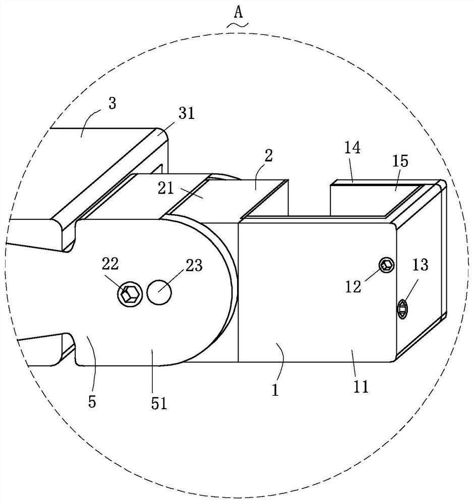
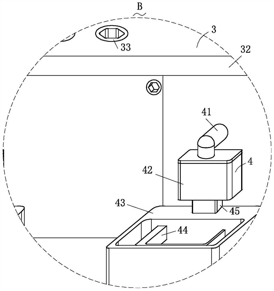
[0026] Such as Figure 1-Figure 7 As shown, a fixing device for robot maintenance according to the present invention includes a limit structure 1, an angle adjustment structure 2, a length adjustment structure 3, a storage structure 4 and a dislocation structure 5; the length for adjusting the limit length The two ends of the adjustment structure 3 are provided with the dislocation structure 5 for staggering the fixed position of the robot power arm, and the two dislocation structures 5 are diagonally symmetrically arranged with respect to the length adjustment structure 3; There is the angle adjustment structure 2 for adjusting the support angle, and the angle adjustment structure 2 is rotationally connected with the dislocation structure 5; the ...


PUM


Abstract

The invention relates to the technical field of robot maintenance equipment, in particular to a fixing device for robot maintenance, including a limit structure, an angle adjustment structure, a length adjustment structure, a storage structure and a dislocation structure; the length adjustment structure for adjusting the support length There are two dislocation structures diagonally and symmetrically at both ends. The setting of the length adjustment structure is convenient for supporting two power arms with different distances, making the operation more convenient and flexible. The setting of the dislocation structure is convenient for two power arms that are not on the same plane. It is convenient to support and limit various types of power arms. The two dislocation structures are arranged diagonally and symmetrically to increase the dislocation distance; one end of the angle adjustment structure is connected to the dislocation structure, and the angle adjustment structure deviates from the dislocation structure. One end is provided with a limit structure, which is convenient to adjust the angle of the limit structure through the angle adjustment structure, so that the limit structure can support the robot power arm with different angles, thereby making the support effect better.

Description

technical field [0001] The invention relates to the technical field of robot maintenance equipment, in particular to a fixing device for robot maintenance. Background technique [0002] Palletizing robots are the product of the organic combination of machinery and computer programs, which provide higher production efficiency for modern production. Palletizing machines are widely used in the palletizing industry. Palletizing robots greatly save labor and space. The stacking robot operates flexibly and accurately, fast and efficiently, with high stability and high operating efficiency. [0003] However, the long-term use of the rotating shaft of the palletizing robot requires regular inspection and dust removal and chip removal. It needs to be replaced after wear and tear. During maintenance, one of the power arms needs to be completely disassembled to replace and clean the rotating shaft. Lifting equipment is required to remove the When the power arm is lifted, the power lin...

Claims


Application Information

Patent Timeline
Patent Type & Authority Patents(China)
IPC IPC(8): B25J19/00B25B11/00
CPCB25B11/00B25J19/00B25J19/0066
Inventor 陈程丽
Owner 玉环精工气动股份有限公司
Learn More