Connecting and separating device based on memory alloy wire driving

A technology for connecting and separating devices and memory alloy wires, which is applied in the aerospace field, can solve problems such as easy generation of redundant substances or polluted gases, poor safety of pyrotechnic devices, and non-repeatable detection, so as to reduce impact, facilitate repeated use, and ensure The effect of reliable separation

Active Publication Date: 2020-07-17
HARBIN INST OF TECH
15 Cites 5 Cited by

AI-Extracted Technical Summary

Problems solved by technology

[0002] The connection and separation release technology is a key technology in the field of aviation weapons and space vehicle technology. The traditional fast-response connection and separation devices usually use p...

Abstract

The invention provides a connecting and separating device based on memory alloy wire driving, which comprises a driving end and a driven end, wherein the driving end comprises a shell, an outer sleeve, a fixed sheet, a compression spring, a rotary sleeve, a base, a memory alloy wire, a guide wheel, a lock pin, a limiting sleeve I and a limiting sleeve II, and the driven end comprises a screw rod,a loading nut, a separating piece and an adapter piece; the upper end of the screw rod is a threaded section matched with the loading nut, and the lower end of the screw rod is provided with multiplelayers of inclined bulges; the multiple layers of inclined bulges extend into the upper part of an accommodating space formed by the limiting sleeve I and the limiting sleeve II; when the memory alloywire is powered on, the memory alloy wire is shortened, the base and the lock pin move upwards, the lock pin relieves limiting of the lower ends of the limiting sleeve I and the limiting sleeve II, the two limiting sleeves rotate simultaneously, the lower portions of the limiting sleeve I and the limiting sleeve II are folded, the upper portions of the limiting sleeve I and the limiting sleeve IIare opened and separated from the screw rod, and the driving end and the driven end are separated. The device realizes rapid separation, and has the advantages of no impact, energy conservation, environmental protection, small size, high reliability and reusability.

Application Domain

Technology Topic

Screw threadEnergy conservation

Image

  • Connecting and separating device based on memory alloy wire driving
  • Connecting and separating device based on memory alloy wire driving
  • Connecting and separating device based on memory alloy wire driving

Examples

  • Experimental program(1)

Example Embodiment

[0036] It should be noted that the embodiments of the present invention and the features in the embodiments can be combined with each other if there is no conflict.
[0037] Hereinafter, the present invention will be described in detail with reference to the drawings and in conjunction with the embodiments.
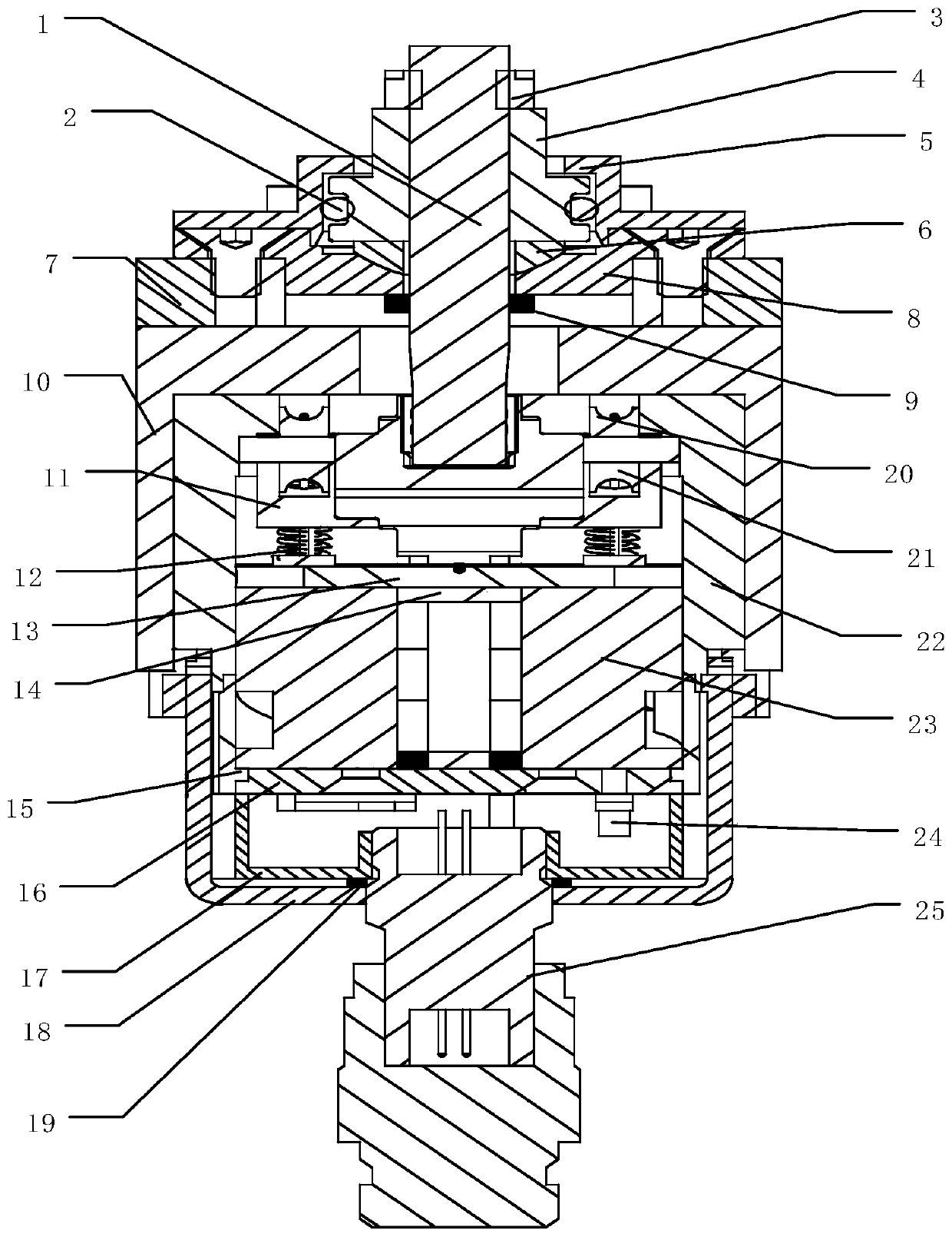
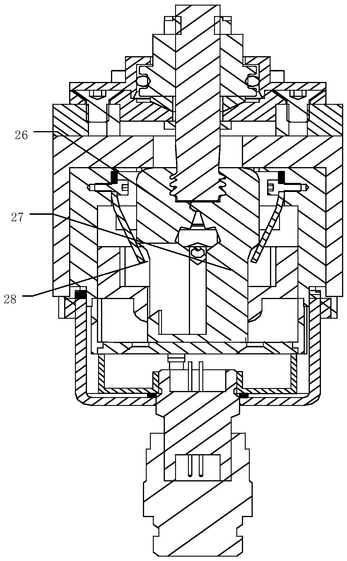
[0038] Such as Figure 1-Figure 7 As shown, a connection and separation device driven by a shape memory alloy wire includes an active end and a passive end. The active end passes through a housing 10, and the passive end is connected to two systems through a separating member 7 respectively. The active end includes a housing 10. Outer jacket 22, fixed piece 11, compression spring 12, rotating sleeve 15, base 16, memory alloy wire 20, guide wheel 21, lock pin 23, limit sleeve Ⅰ 26 and limit sleeve Ⅱ 27;
[0039] The outer casing 22 is coaxially fixed in the housing 10, and the limit sleeve I 26, the limit sleeve II 27, the fixing piece 11, the guide wheel 21 and the lock pin 23 are all arranged in the outer sleeve 22. Position sleeve I 26 and limit sleeve II 27 are arranged in the middle of the housing 22, and the openings of the limit sleeve I 26 and the limit sleeve II 27 are arranged oppositely to enclose a containing space; a fixing piece 11 is fixedly arranged on each side of the outer casing 22, and each Each fixing piece 11 is equipped with a guide wheel 21 through a pin shaft. The central axis connection of the two guide wheels 21 is perpendicular to the connection space between the limit sleeve I 26 and the limit sleeve II 27; the top of the lock pin 23 is from the outer casing The bottom end of 22 extends into the outer casing 22, and the lock pin 23 is slidably arranged in the outer casing 22; the bottom ends of the limit sleeve I 26 and the limit sleeve II 27 extend into the through hole in the middle of the lock pin 23, and the lock pin 23 limits the The lower circumferential restraint of the position sleeve Ⅰ 26 and the limit sleeve Ⅱ 27;
[0040] The base 16 is fixed at the bottom of the lock pin 23, a memory alloy wire 20 is wound on each guide wheel 21, and both of each memory alloy wire 20 pass through the lock pin 23 and are fixed on the base 16; A rotary sleeve 15 is sleeved on the lock pin 23, a spiral groove 36 is provided on the outer surface of the lock pin 23, and correspondingly, a protrusion 37 matching the spiral groove 36 is provided on the inner wall of the rotary sleeve 15 When the lock pin 23 moves up and down, the rotary sleeve 15 rotates forward and backward; a compression spring 12 is provided between the upper surface of the lock pin 23 and the fixed piece 11, and the compression spring 12 keeps the lock pin 23 locked Tight state
[0041] The passive end includes a screw 1, a loading nut 4, a separating piece 7 and an adapter 8; the adapter 8 is coaxially fixed on the separating piece 7, and the upper end of the screw 1 is connected to the loading nut 4 With the matching thread section, the lower end of the screw 4 is provided with multiple inclined protrusions 29, and the multiple inclined protrusions 29 are arranged symmetrically along the axis of the screw 1; the multiple inclined protrusions 29 at the lower end of the screw 1 pass through the rotation in turn The through hole at the center of the connecting piece 8, the through hole at the upper end of the housing 10, and the through hole at the upper end of the outer casing 22 extend into the upper part of the containing space formed by the limit sleeve I 26 and the limit sleeve II 27;
[0042] The memory alloy wire 20 is shortened when energized, the base 16 and the lock pin 23 move up, and the lock pin 23 releases the limit on the lower end of the limit sleeve I26 and the limit sleeve Ⅱ27. The limit sleeve Ⅰ26 and the limit sleeve Ⅱ27 rotate at the same time to limit the position. The lower part of the sleeve I 26 and the limit sleeve Ⅱ 27 are folded, and the upper part of the limit sleeve I 26 and the limit sleeve Ⅱ 27 are opened and separated from the screw 1 to realize the separation of the active end and the passive end.
[0043] The accommodating space formed by the limit sleeve Ⅰ26 and the limit sleeve Ⅱ27 is, from top to bottom, a chute section 30, a flared groove section 31, and a straight groove section that cooperate with the multilayer inclined protrusion 29 at the end of the screw 1 32. The chute section 30 and the flaring groove section 31 are separated by a revolving hinge; the revolving hinge consists of a semi-circular groove 33 arranged on the limit sleeve I 26 and the limit sleeve II 27 The semicircular protrusions 34 are formed in cooperation with each other; at the lower part of the limit sleeve I 26 are two limit hooks 35 arranged in parallel, and at the lower part of the limit sleeve II 27 are a limit hook, and the two limit sleeves I 26 There is a gap between the limit hooks for accommodating the limit hooks of the limit sleeve Ⅱ 27; the lock pin 23 limits the swing of the three limit hooks 35.
[0044] An inclined block 14 is installed on the upper end of the lock pin 23 through the optical axis 13. The inclined block 14 is arranged in the space below the hinge of the limit sleeve I 26 and the limit sleeve II 27, and the optical axis 13 passes through the limit sleeve. The space below the rotary hinge of the position sleeve Ⅰ 26 and the limit sleeve Ⅱ 27 is arranged.
[0045] A bottom cover 17 is installed below the base 16, and the bottom cover 17 is threadedly connected with the electrical connector 25. A bottom sealing cover 18 is covered on the bottom cover 17 and the screw sleeve 15. The bottom sealing cover 18 and the housing 10 Threaded connection at the lower end.
[0046] One end of each memory alloy wire 20 is fixed on the base 16 through a connection terminal 24, and the two connection terminals of the two memory alloy wires are both connected to the electrical connector 25 through wires.
[0047] Two reeds 28 for rotating the limit sleeve I 26 and the limit sleeve II 27 are fixed on the outer casing 22, and each reed 28 is arranged on the outside of the corresponding limit sleeve.
[0048] A spherical gasket 6 is provided at the contact point between the adapter 8 and the loading nut 4, and the spherical gasket 6 is sleeved on the screw 1; a screw seal 9 is sleeved on the screw at the bottom of the adapter 8; An upper sealing cover 5 is covered on the loading nut 4, and a sealing ring 2 is provided at the circumferential contact surface of the upper sealing cover 5 and the loading nut 5.
[0049] The rotary sleeve 15 has a reset mark point, and the housing 10 is also provided with a reset mark point. The reset mark point on the rotary sleeve 15 to the rotary sleeve 15 coincides with the reset mark point on the housing 10, and the active end And the passive end is reset.
[0050] A bottom sealing ring 19 is sleeved on the electrical connector 25 between the bottom cover 17 and the bottom sealing cover 18.
[0051] A thin nut 3 for preventing loosening is added to the upper part of the loading nut 4. The memory alloy wire 20 is a one-way memory alloy wire, which can be shortened when energized.
[0052] The lock pin 23, the guide wheel 21, and the bottom cover 17 are made of nylon to ensure that the contact position between the memory alloy wire 20 and the connection terminal 24 is insulated.
[0053] The working process of the present invention:
[0054] 1. Separation process:
[0055] The memory alloy wire 20 is shortened after being energized, and drives the bottom cover 17, the base 16, the lock pin 23 and the inclined block 14 to move up. The lower end of the lock pin 23 can simultaneously release the limit sleeve I26 and the limit hook 35 under the limit sleeve II27. Constrained, when the inclined block 14 moves up to the flared groove section 31 composed of the limit sleeve I 26 and the limit sleeve II 27, the pre-tightening force on the screw 1 passes through the multi-layer inclined protrusions 29 to the limit sleeve I 26 and the limit sleeve II 27 At the same time, with the assistance of the reeds 28 on both sides, the limit sleeve I 26 and the limit sleeve Ⅱ 27 are rotated around the rotary hinge composed of the semi-circular protrusion 34 and the semi-circular groove 33, namely the limit sleeve I 26 and the limit sleeve. The lower part of the position sleeve Ⅱ27 is folded, the upper part of the limit sleeve Ⅰ26 and the limit sleeve Ⅱ27 are opened and separated from the screw 1, and the passive end can be transferred with the separation system.
[0056] 2. Reset process:
[0057] As the lock pin 23 moves up during the separation process, there are two spiral grooves 36 on the outside of the lock pin 23 corresponding to the protrusions 37 on the rotary sleeve 15, and the rotary sleeve 15 has been rotated forward; when reset, it will be passive Put the end back, put the screw 1 into the upper chute section 31 of the limit sleeve Ⅰ26 and the limit sleeve Ⅱ27, and rotate the sleeve 15 in the opposite direction. As the sleeve 15 rotates, the lock pin 23 moves downward, driving the inclined block 14 Move down, the upper part of the limit sleeve Ⅰ26 and the limit sleeve Ⅱ27 are closed, and contact with the multi-layer inclined protrusion 29 on the screw 1, the memory alloy wire 20 is stretched back to the original length, and the rotary sleeve 15 is reversely rotated to the reset mark point It coincides with the marking point on the housing 10, the reset action is completed, a torque is applied to the loading nut 4, and the screw 1 generates an axial pre-tightening force. The return lower ends of the limit sleeve I 26 and the limit sleeve II 27 are on the inner wall of the lock pin 23 and Under the constraint of the inclined block 14, it will not open or drive the lock pin 23 to move, which increases the reliability of the locked state.
[0058] The above descriptions are only preferred embodiments of the present invention and are not intended to limit the present invention. Any modification, equivalent replacement, improvement, etc. made within the spirit and principle of the present invention shall be included in the present invention. Within the scope of protection.

PUM

no PUM

Description & Claims & Application Information

We can also present the details of the Description, Claims and Application information to help users get a comprehensive understanding of the technical details of the patent, such as background art, summary of invention, brief description of drawings, description of embodiments, and other original content. On the other hand, users can also determine the specific scope of protection of the technology through the list of claims; as well as understand the changes in the life cycle of the technology with the presentation of the patent timeline. Login to view more.

Similar technology patents

Deep water stone throwing method and device

InactiveCN104988926AReduce shockDeep waterFoundation engineeringEngineeringFall detection
Owner:SHENZHEN OFFSHORE OIL ENG UNDERWATER TECH

Automobile dual-mass flywheel with continuous varied stiffness and high torque

InactiveCN102230512AReduce shockAvoid shock loads and noiseFlywheelsFlywheelHigh torque
Owner:CHONGQING UNIV

Classification and recommendation of technical efficacy words

  • Reduce size and mass
  • Reduce shock

Solid cool air micro-propelling system

InactiveCN103921956AReduce size and massImprove propulsion efficiencyCosmonautic propulsion system apparatusSolid nitrogenPropulsive efficiency
Owner:NANJING UNIV OF SCI & TECH

Sealed small low-impact release screw bolt

InactiveCN101875404AReduce shockStrong connectionCosmonautic component separationPistonMissile
Owner:BEIJING INSTITUTE OF TECHNOLOGYGY

Method for realizing fast coal exposing of coal seam rock cross with outburst danger

InactiveCN101598030AReduce shockBuffer and isolate the impactGas removalCoalPetrology
Owner:CHINA UNIV OF MINING & TECH
Why Eureka
Try Eureka