Foundation pit supporting structure

A technology for supporting structures and foundation pits, which is applied in infrastructure engineering, excavation, construction, etc., can solve the problems that foundation pit support structures cannot be applied to large-span foundation pits, etc., to save engineering materials and time, improve stability, and be universal sexual effect

Pending Publication Date: 2020-07-17
SHANGHAI MECHANIZED CONSTR GRP +2
View PDF0 Cites 2 Cited by
  • Summary
  • Abstract
  • Description
  • Claims
  • Application Information

AI Technical Summary

Problems solved by technology

[0005] In view of the above reasons, the object of the present invention is to provide a foundation pit support structure, the application of which can effectively solve the problem that the foundation pit support structure in the prior art cannot be applied to large-span foundation pits

Method used


Image

  • Foundation pit supporting structure
  • Foundation pit supporting structure

Examples


Embodiment 1

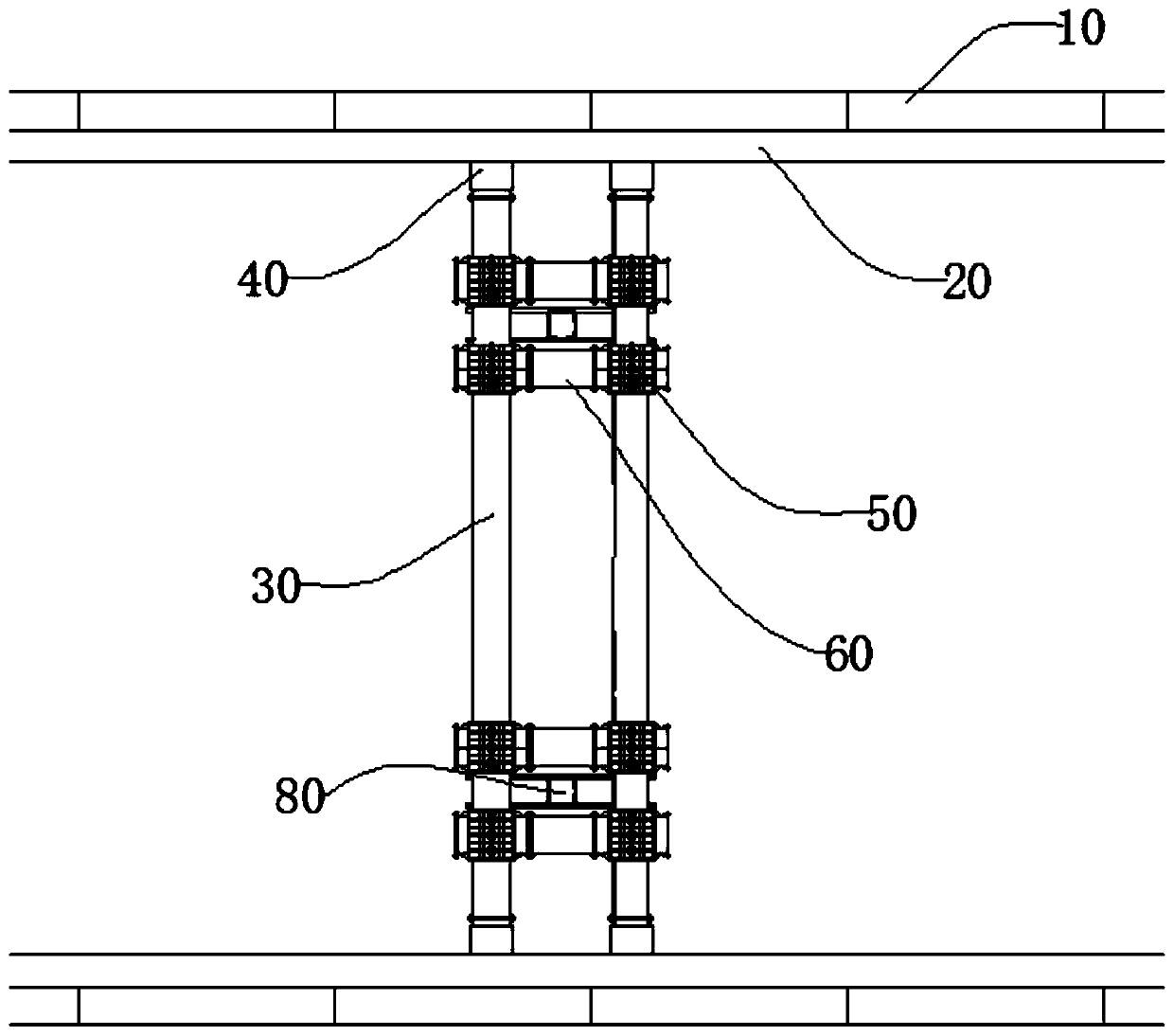
[0026] figure 1 For the schematic diagram of the foundation pit support structure provided by Embodiment 1 of the present invention, refer to figure 1 , The supporting structure of the foundation pit in this embodiment includes a steel purlin 20 , a supporting steel pipe 30 , an oil cylinder 40 , a movable cross 50 , a first connecting rod 60 and a bottom fixing member 80 . Two steel purlins 20 are respectively erected on two opposite side walls 10 of the foundation pit for fixing the side walls 10 of the foundation pit; one end of the oil cylinder 40 is fixed on the steel purlins 20, and the other end is fixed on the supporting steel pipe 30, A support steel pipe 30 and two oil cylinders 40 form a support group, the active cross 50 is set on the support steel pipe 30, and the first connecting steel pipe 60 is used to connect the two active cross 50 with flanges to realize the connection between the two support groups. Two bottom fixing parts 80 are fixed on the bottom of the...

Embodiment 2

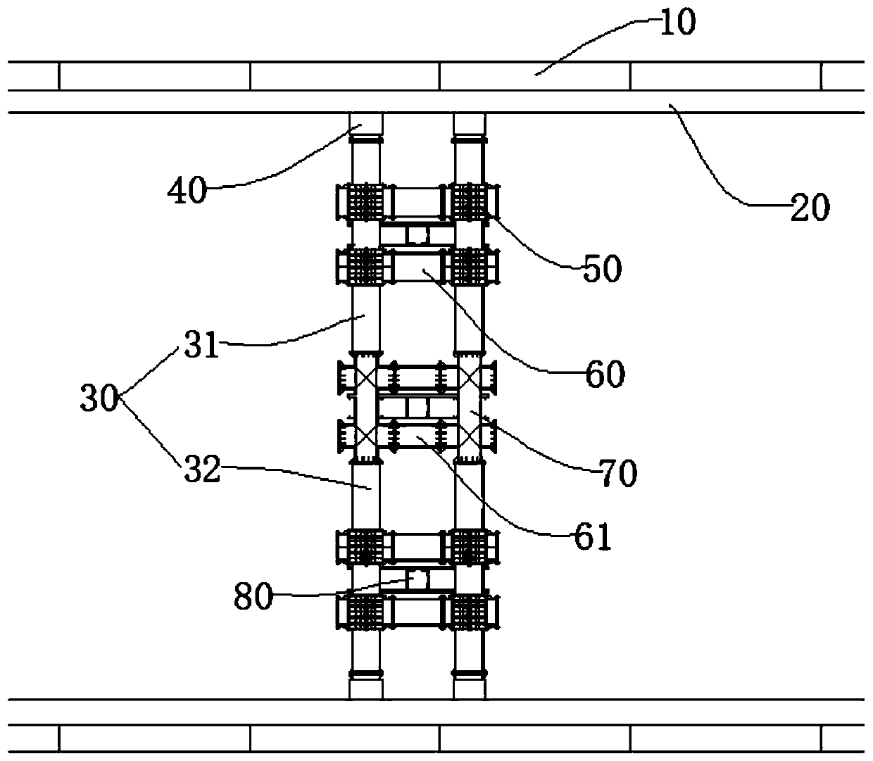
[0030] figure 2 For the schematic diagram of the foundation pit support structure provided by Embodiment 2 of the present invention, refer to figure 2 , the foundation pit supporting structure of the present embodiment comprises steel purlin 20, supporting steel pipe 30, oil cylinder 40, active four-way 50, first connecting rod 60, second connecting steel pipe 61, fixed six-way 70 and bottom fixing piece 80, supports The steel pipe 30 is divided into two sections, namely a first supporting steel pipe 31 and a second supporting steel pipe 32 . Two steel purlins 20 are respectively erected on two opposite side walls 10 of the foundation pit for fixing the side walls 10 of the foundation pit; one end of the oil cylinder 40 is fixed on the steel purlins 20, and the other end is fixed on the first supporting steel pipe 31 One end of the second supporting steel pipe 32, the other end of the first supporting steel pipe 31 and the other end of the second supporting steel pipe 32 ar...


PUM


Abstract

The invention provides a foundation pit supporting structure. The foundation pit supporting structure is used for supporting a foundation pit. The foundation pit supporting structure comprises a plurality of bottom fixing parts, connecting parts and a plurality of supporting groups. Each support grouping comprises two telescopic parts and a supporting rod. One ends of the every two telescopic parts are separately fixed to two ends of each supporting rod, the other ends of the every two telescopic parts are separately fixed on the two opposite side walls of the foundation pit, and the telescopic parts can be stretched out and drawn back; the supporting groups are arranged at intervals in the first direction, and the supporting groups are connected through the connecting parts; and the bottom fixing parts are fixed to the bottom of the foundation pit, each supporting group is erected on at least one bottom fixing part, the first direction is parallel to the bottom surface of the foundation pit and perpendicular to the extension direction of the supporting groups. The foundation pit supporting structure can effectively solve the problem that a foundation pit supporting structure in the prior art cannot be applied to a large-span foundation pit.

Description

technical field [0001] The invention relates to the construction field of foundation pit support engineering, in particular to a foundation pit support structure. Background technique [0002] Foundation pit support refers to the support, reinforcement and protection measures adopted for the side wall of the foundation pit and the surrounding environment in order to ensure the safety of the underground structure construction and the surrounding environment of the foundation pit. Whether it is a high-rise building or a deep foundation pit project for subway construction, since most of them are excavated in cities, there are usually various structures such as traffic arteries, existing buildings or pipelines around the foundation pit. It is necessary to protect the surrounding structures of the foundation pit. Safe use makes foundation pit support a very important part of foundation pit excavation. At present, foundation pit support systems in soft soil areas include concrete...

Claims


Application Information

Patent Timeline
Patent Type & Authority Applications(China)
IPC IPC(8): E02D17/04
CPCE02D17/04E02D2300/0029E02D2600/20
Inventor 周铮贾坚史普中周蓉峰谢小林金晶滕延锋翟杰群张志彬胡东史志军
Owner SHANGHAI MECHANIZED CONSTR GRP
Why Eureka
Try Eureka