Supercharge Your Innovation With Domain-Expert AI Agents!

Novel electric heater

An electric heater, a new type of technology, applied in the field of electric heaters, can solve the problems of unresolved air supply range, complex overall structure of electric heaters, and single function, and achieve convenient and fast rotation operation, convenient moving electric heaters, Easy operation and simple effect

Pending Publication Date: 2020-07-17
中山市鑫能电器制造有限公司
View PDF0 Cites 1 Cited by
  • Summary
  • Abstract
  • Description
  • Claims
  • Application Information

AI Technical Summary

Problems solved by technology

[0002] Electric heaters have heating functions and are widely used by people; in order to expand the heating range of electric heaters or switch the direction of air supply, the following solutions are generally adopted for existing electric heaters: ①The outer shell is set to be rotatable as a whole, and the outer shell Reciprocating rotation within a certain angle range, so that the warm air is blown within a certain angle range, thereby expanding the heating range, but due to the overall rotation of the outer shell, it is easily affected by external factors (when there is a foreign object blocking it, it is easy to hinder the normal rotation of the outer shell); ②Set swingable blades at the air outlet. The swinging blades have the function of guiding the wind, and the wind can be swept or switched by swinging the blades. However, the air supply range of this structure is limited, and the blades are easy to be damaged; ③A wind guide is installed on the air duct The wind direction can be switched by flipping the wind deflector, but the switchable wind direction is limited (generally only two wind directions can be switched), and the wind sweeping cannot be realized, and the air supply range has not yet been solved
[0003] Most of the electric heaters on the market generally have a clothes drying function, which is mainly achieved by setting a corresponding clothes drying rack on the electric heater, hanging the clothes on the clothes drying rack and cooperating with the electric heater to blow warm air to achieve drying. Effect; the existing clothes racks on electric heaters generally need to be opened or stored through complex operations, and the clothes racks generally only have the function of hanging clothes, and the function is single
In addition, in order to allow the electric heater to stand stably on the plane, the bottom of the electric heater is generally provided with supporting feet. The existing feet only have the function of supporting the electric heater on the plane; when the electric heater can stand on the plane When used, it can also be hung on the wall for drying clothes. Setting the feet and drying rack at the same time will make the overall structure of the electric heater look complicated, and the operation will be more troublesome.

Method used


Image

  • Novel electric heater
  • Novel electric heater
  • Novel electric heater

Examples


no. 1 example

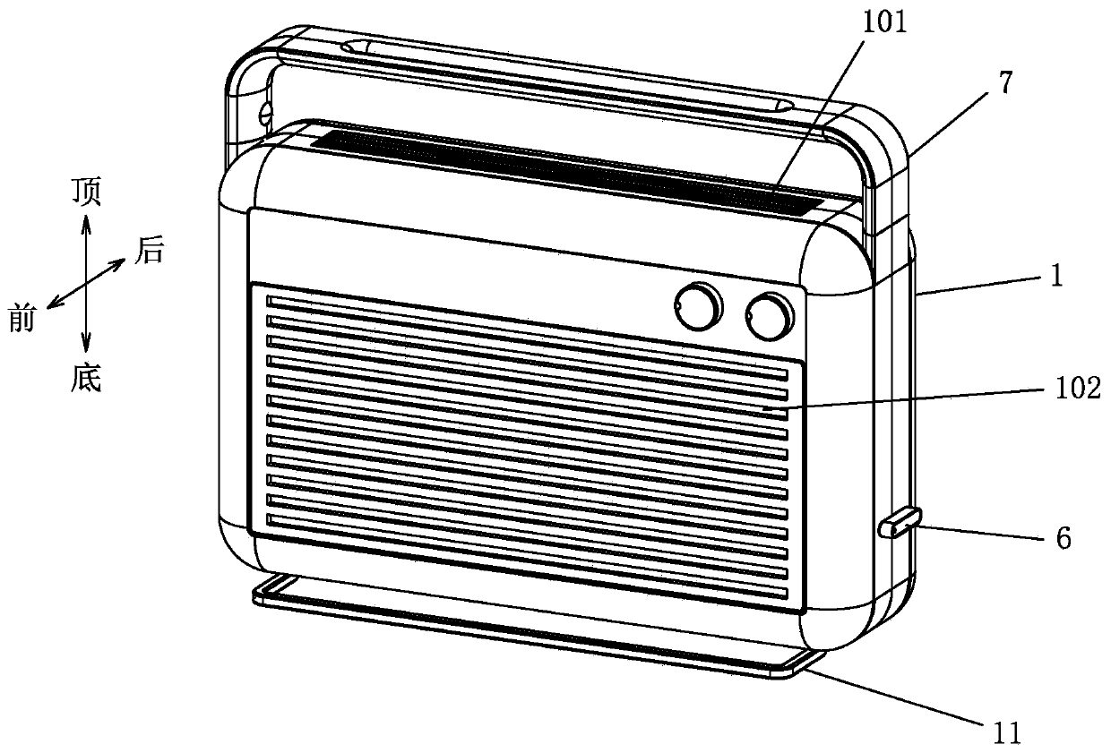
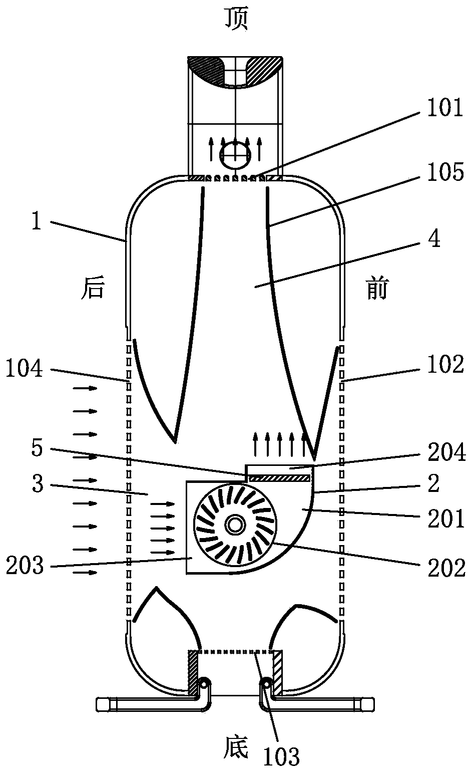
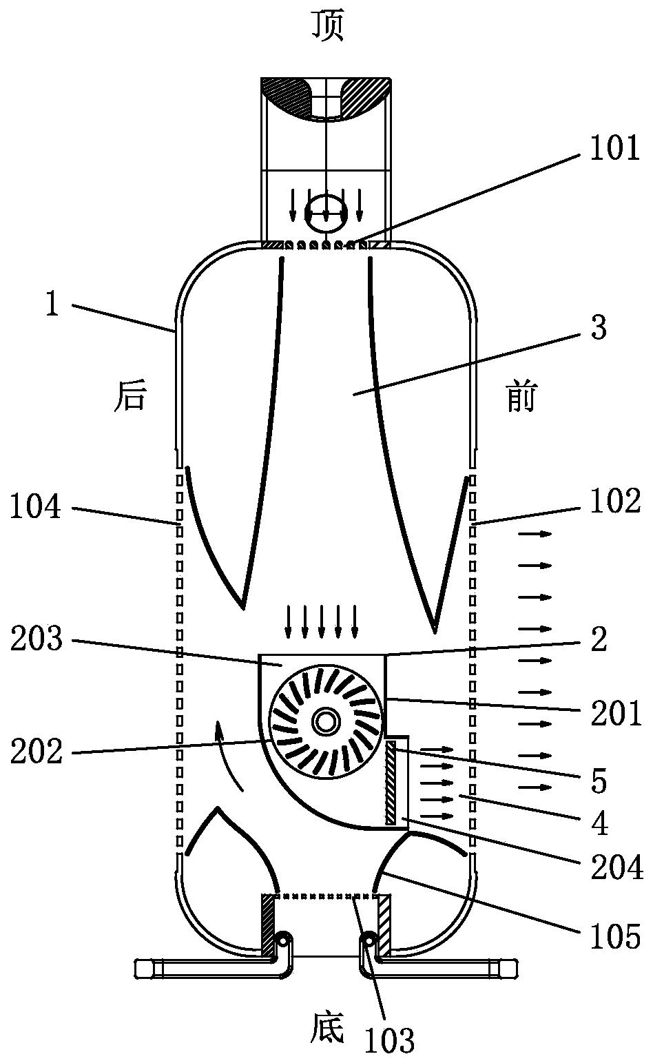
[0038] See Figure 1-Figure 13 , The electric heater involved in this embodiment includes an outer casing 1 and a fan assembly 2; two or more ventilation structures are provided at different positions on the outer casing 1, and each ventilation structure faces different directions; the fan assembly 2 is rotatable as a whole The air inlet 203 on the fan assembly 2 is connected to the corresponding ventilation structure as the fan assembly 2 rotates relative to the outer housing 1, and the air outlet 204 on the fan assembly 2 is connected to the corresponding ventilation structure. The structure is connected, the air inlet duct 3 is formed between the air inlet 203 and the corresponding ventilation structure, and the air outlet duct 4 is formed between the air outlet 204 and the corresponding ventilation structure; the outer casing 1 is provided with a lifting device that can switch different functional forms. The handle 7 and the feet 11, and the handle 7 and the feet 11 respecti...

no. 2 example

[0058] See Figure 14 The electric heater involved in this embodiment is different from the first embodiment in that: the ventilation structure is a number of circumferential ventilation holes 106 opened on the 360° circumferential side of the outer shell 1; the outer shell 1 is preferably cylindrical, using a rotating fan The principle of assembly 2 enables this electric heater to achieve 360°out of wind without dead ends.

[0059] The other undescribed parts are the same as the first embodiment, and no detailed analysis and description are omitted here.

no. 3 example

[0061] See Figure 15 The electric heater involved in this embodiment is different from the first embodiment in that the ventilation structure is a front ventilation hole 102 opened on the front side of the outer housing 1, a rear ventilation hole 104 on the rear side, and a left ventilation hole 107 on the left side. , And the right vent 108 on the right side; therefore, the electric heater involved in this embodiment has the effect of front, rear, left, and right air vents.

[0062] The other undescribed parts are the same as the first embodiment, and no detailed analysis and description are omitted here.


PUM


Abstract

The invention relates to a novel electric heater. The novel electric heater comprises an outer shell and a fan assembly, and is characterized in that two or more sets of ventilation structures are arranged on the outer shell, and the ventilation structures face different directions; the fan assembly is overall rotationally arranged on the outer shell, along with rotating of the fan assembly relative to the outer shell, an air inlet on the fan assembly communicates with the corresponding ventilation structure, and an air outlet on the fan assembly communicates with the corresponding ventilationstructure; and handles and / or supporting feet capable of switching different function states are arranged on the outer shell, and the handles and / or supporting feet correspond to the corresponding ventilation structures. The electric heater can be freely switched between multiple functions and purposes, operation is convenient, performance is reliable, and different use requirements of users aremet.

Description

Technical field [0001] The invention relates to an electric heater, in particular to a new type of electric heater. Background technique [0002] Electric heaters have a heating function and are widely used. In order to expand the heating range of electric heaters or switch the direction of air supply, the existing electric heaters generally adopt the following solutions: ① The overall outer casing is set to be rotatable, and the outer casing is The reciprocating rotation within a certain angle range makes the warm air blow within a certain angle range, thereby expanding the heating range. However, due to the overall rotation of the outer casing, it is easily affected by external factors (it is easy to hinder the normal rotation of the outer casing when blocked by foreign objects); ②Set up swingable blades at the air outlet. The swinging blades have the function of guiding the wind. Sweeping or switching the wind direction can be achieved by swinging the blades. However, the air ...

Claims


Application Information

Patent Timeline
Patent Type & Authority Applications(China)
IPC IPC(8): F24D13/00F24D19/00F24D19/02F24D19/06D06F57/12
CPCF24D13/00F24D19/06F24D19/00F24D19/0213D06F57/12F24D2200/08
Inventor 杜岩
Owner 中山市鑫能电器制造有限公司
Features
  • R&D
  • Intellectual Property
  • Life Sciences
  • Materials
  • Tech Scout
  • Unparalleled Data Quality
  • Higher Quality Content
  • 60% Fewer Hallucinations
Learn More