
A transformer temperature measurement system and measurement method

A temperature measurement and transformer technology, applied in the field of power transformer operation monitoring, can solve the problems of increasing error, the accuracy of calculation results cannot be guaranteed, and the calculation parameters cannot be matched, so as to achieve the effect of improving accuracy

Active Publication Date: 2021-10-26
甘书宇
View PDF10 Cites 0 Cited by
  • Summary
  • Abstract
  • Description
  • Claims
  • Application Information

AI Technical Summary

Problems solved by technology

The problem with this method is that the temperature sensor of the measurement and control device is not the same as the oil surface thermometer and temperature sensor installed on the transformer body, and the installation positions are different, and the transmission circuits are also different.
There are some deficiencies in this scheme: First, the current adopts the form of current transformer to collect the transformer load current on site, and there is an open circuit of the current loop, which will cause equipment and personal safety risks; The error is increased; the third is that there are many electronic components and circuits in the field device, and the environmental factors are greatly affected; the fourth is that the calculation method is fixed, and the calculation parameters are fixed. The calculation parameters cannot be matched with different transformer operating parameters, and the accuracy of the calculation results cannot be guaranteed. , the method is not universal
[0005] At present, relevant research and solutions have problems such as poor reliability of electronic equipment, complex loop repetition, many forwarding links, external factors affecting measurement accuracy and transmission accuracy, and safety risks caused by current loops. There is no effective solution to solve the problems in the background technology. stated question

Method used


Image

  • A transformer temperature measurement system and measurement method
  • A transformer temperature measurement system and measurement method
  • A transformer temperature measurement system and measurement method

Examples


Embodiment 1

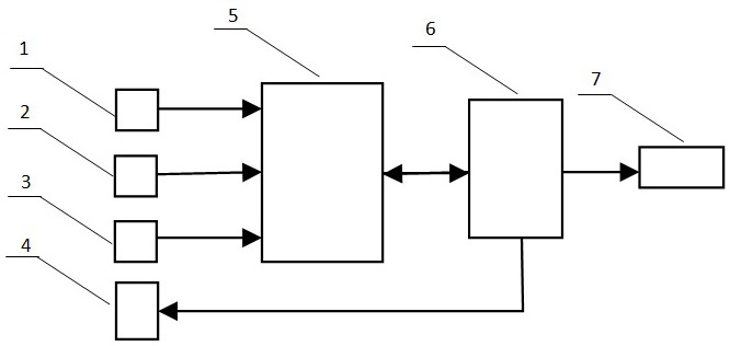
[0076] Refer to attached figure 1 , the realization scheme adopts technical scheme one.

[0077] Specific data of the measured transformer:

[0078] Product model: SFPSZ10-180000 / 220

[0079] Rated capacity: 180 / 180 / 90MVA

[0080] Rated current: 472 / 900 / 4950A

[0081] Cooling method: ODAF

[0082] The steady-state temperature rise data of the top layer oil temperature under the rated loss reported by the factory: 55K

[0083] Gradient data of hot spot temperature to top oil temperature at rated current: 10K

[0084] All four sets of radiators are configured and put into operation.

[0085] The transformer oil level temperature sensor 1 is placed in the temperature sensor installation slot on the top of the transformer, and is used to measure the oil level temperature inside the transformer. The sensor uses a Pt100 temperature sensor, which outputs a resistance signal that changes with temperature, and the output signal is connected to the transformer measurement and contr...

Embodiment 2

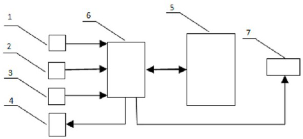
[0132] Refer to attached figure 2 , the realization scheme adopts the technical scheme two.

[0133] In the figure: transformer oil surface temperature sensor 1, transformer ambient temperature sensor 2, transformer cooling system operation sensor 3, transformer temperature local display unit 4, transformer substation automation system transformer measurement and control equipment 5, transformer temperature management unit 6, transformer temperature remote Display unit 7.

[0134] Specific data of the measured transformer:

[0135] Product model: SFPSZ10-180000 / 220

[0136] Rated capacity: 180 / 180 / 90MVA

[0137] Rated current: 472 / 900 / 4950A

[0138] Cooling method: ODAF

[0139] The steady-state temperature rise data of the top layer oil temperature under the rated loss reported by the factory: 55K

[0140] Gradient data of hot spot temperature to top oil temperature at rated current: 10K

[0141] All four sets of radiators are configured and put into operation.

[0142...

Embodiment 3

[0167] Refer to attached figure 2 , the realization scheme adopts the technical scheme two.

[0168] In the figure: transformer oil surface temperature sensor 1, transformer ambient temperature sensor 2, transformer cooling system operation sensor 3, transformer temperature local display unit 4, transformer substation automation system transformer measurement and control equipment 5, transformer temperature management unit 6, transformer temperature remote Display unit 7.

[0169] Specific data of the measured transformer:

[0170] Product model: SSZ10-50000 / 110

[0171] Rated capacity: 50MVA

[0172] Rated current: 262A

[0173] Cooling method: ONAN

[0174] The steady-state temperature rise data of the top layer oil temperature under the rated loss reported by the factory: 55K

[0175] Gradient data of hot spot temperature to top oil temperature at rated current: 10K

[0176] The transformer oil level temperature sensor 1 is placed in the temperature sensor installat...


PUM


Abstract

The invention relates to a transformer temperature measuring system and a measuring method, which are used for measuring the oil surface temperature and winding temperature of an oil-immersed transformer. The technical solution is: obtain the operation status of the transformer cooling system through the operation status sensor of the transformer cooling system, and adjust the calculation parameters; obtain the transformer load current value through data communication; check the validity of the transformer oil surface temperature data; calculate the transformer Winding temperature value; transmit the value of transformer oil surface temperature and winding temperature to the transformer temperature remote display unit and transformer temperature local display unit simultaneously by means of data communication. The invention can effectively improve the temperature measurement accuracy of the oil-immersed transformer, simplify equipment configuration and circuits at the same time, and improve the technical level of oil-immersed transformer monitoring.

Description

technical field [0001] The invention relates to a transformer temperature measurement system and a measurement method, which are used for measuring the oil surface temperature and winding temperature of an oil-immersed transformer, and belong to the technical field of power transformer operation monitoring. Background technique [0002] The oil-immersed transformer is a very important substation equipment in the power system, and its safe and stable operation is related to the safety and stability of the entire power system. The oil surface temperature and winding hot spot temperature of an oil-immersed transformer are important data to characterize the operating state of the transformer. In order to measure the oil surface temperature and winding hot spot temperature of the transformer, a temperature probe slot will be installed on the top of the running transformer in engineering. The probe slot goes deep into the transformer oil inside the transformer. The probe slot is...

Claims


Application Information

Patent Timeline
Patent Type & Authority Patents(China)
IPC IPC(8): G01K7/18G01R31/00
CPCG01K7/18G01R31/00
Inventor 甘书宇
Owner 甘书宇
Learn More