Bottle body defect visual detection device

A visual inspection device and bottle body technology, used in measurement devices, optical testing of defects/defects, material analysis by optical means, etc., can solve problems such as inability to detect defects, eliminate shooting dead angles, clear images, and improve shooting accuracy. Effect

Pending Publication Date: 2020-07-17
北京妙想科技有限公司
View PDF11 Cites 2 Cited by
  • Summary
  • Abstract
  • Description
  • Claims
  • Application Information

AI Technical Summary

Problems solved by technology

[0005] The above-mentioned existing technical solutions have the following defects: when the bottle body 1 is detected, the bottle body 1 follows the conveyor belt and advances to the lower side of the lighting source, and the light emitted by the lighting source shines on the bottle body 1, and the bottle body 1 Light up, the camera takes pictures of the bottle body 1, displays the image of the bottle body 1 through the computer, and detects the defects on the bottle body 1
But in actual detection, since the bottle body 1 is directly placed on the conveyor belt, and the lighting source is arranged on the upper side of the bottle body 1, when the lighting source illuminates the bottle body 1 and takes pictures, the light source emitted by the lighting source cannot Through the bottom of the bottle 102, making it impossible to detect defects on the bottom of the bottle 102 more intuitively

Method used


Image

  • Bottle body defect visual detection device
  • Bottle body defect visual detection device
  • Bottle body defect visual detection device

Examples


Embodiment Construction

[0046] The present invention will be described in further detail below in conjunction with the accompanying drawings.

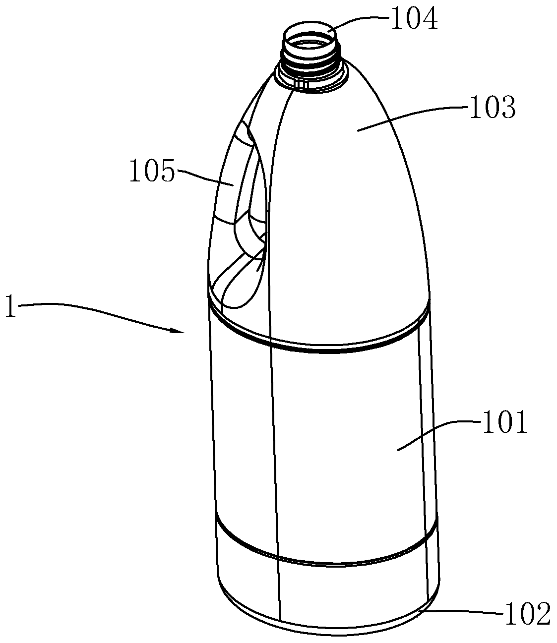
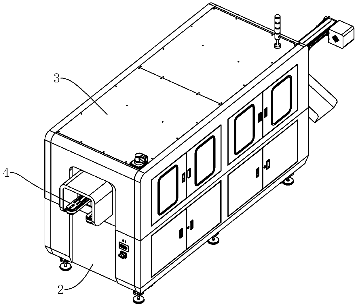
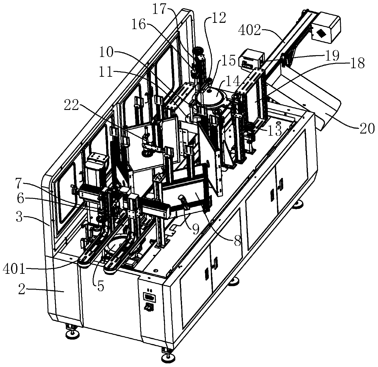
[0047] refer to figure 2 , image 3 , is a bottle body defect visual detection device disclosed by the present invention, comprising a main body 2, and a closing cover 3 is arranged on the main body 2. On the main body 2, a conveying assembly 4 for conveying the bottle body 1 is arranged.

[0048] refer to image 3 , Figure 4 , the conveying assembly 4 includes two primary conveying belts 401 arranged in the same horizontal plane, and the conveying assembly 4 is installed on the main body 2 . There is a gap between the two primary conveyor belts 401 . After the bottle body 101 enters the main body 2, it enters between two primary conveyor belts 401, and the two primary conveyor belts 401 clamp the bottle body 101, and the two primary conveyor belts 401 transport the bottle body 101 forward through clamping . Wherein, when the two primary conveyor bel...


PUM


Abstract

The invention relates to a bottle body defect visual detection device which comprises a main machine body. A conveying assembly used for conveying bottle bodies is arranged on the main machine body; the conveying assembly comprises two primary conveying belts arranged in the same horizontal plane, a gap exists between the two primary conveying belts, and the two primary conveying belts convey bottle bodies forwards through clamping. A first illuminating lamp, a fifth shooting camera and a first shooting camera are further installed on the main machine body, the first illuminating lamp is arranged on the lower sides of the two primary conveying belts, the first shooting camera is located on the upper side of the first illuminating lamp, a center hole is formed in the first illuminating lamp, and the fifth shooting camera is arranged on the lower side of the first illuminating lamp; the first illuminating lamp illuminates upwards, the fifth shooting camera shoots upwards, and the fifth shooting camera shoots upwards through a center hole of the first illuminating lamp. The device has the advantages that the shot bottle body image is clearer, and whether defects exist on the bottle body or not can be seen more visually.

Description

technical field [0001] The invention relates to the technical field of bottle body defect detection, in particular to a bottle body defect visual detection device. Background technique [0002] With the intensification of the trend of global economic integration, the plastic bottle manufacturing industry has higher and higher requirements for product quality, forcing companies and enterprises in related industries to invest more human and financial resources in product quality inspection. In the production process of plastic bottles, the defect of the bottle body is an important aspect to measure the quality of the product. The plastic bottles with bad defects in the bottle body will not only cause complaints and claims from customers, but also bring unpredictable reputation and economic losses to the manufacturer, which will directly affect the market image of the manufacturer and damage the reputation of customers. Benefit. [0003] Such as figure 1 As shown, the existi...

Claims


Application Information

Patent Timeline
Patent Type & Authority Applications(China)
IPC IPC(8): G01N21/90G01N21/88G01N21/01
CPCG01N21/90G01N21/909G01N21/9009G01N21/8851G01N21/8806G01N21/01G01N2021/8809G01N2021/8841G01N2021/887G01N2021/0112
Inventor 李云峰沈志山修英杰李家杰张健李亚明赵星宇
Owner 北京妙想科技有限公司
Why Eureka
Try Eureka