Display panel, alignment method thereof and display device
A display panel and alignment layer technology, applied in nonlinear optics, instruments, optics, etc., can solve problems such as weak anchoring ability, easy to produce afterimages, and affect the quality of the display.
- Summary
- Abstract
- Description
- Claims
- Application Information
AI Technical Summary
Problems solved by technology
Method used
Image
Examples
Embodiment 1
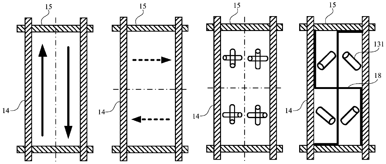
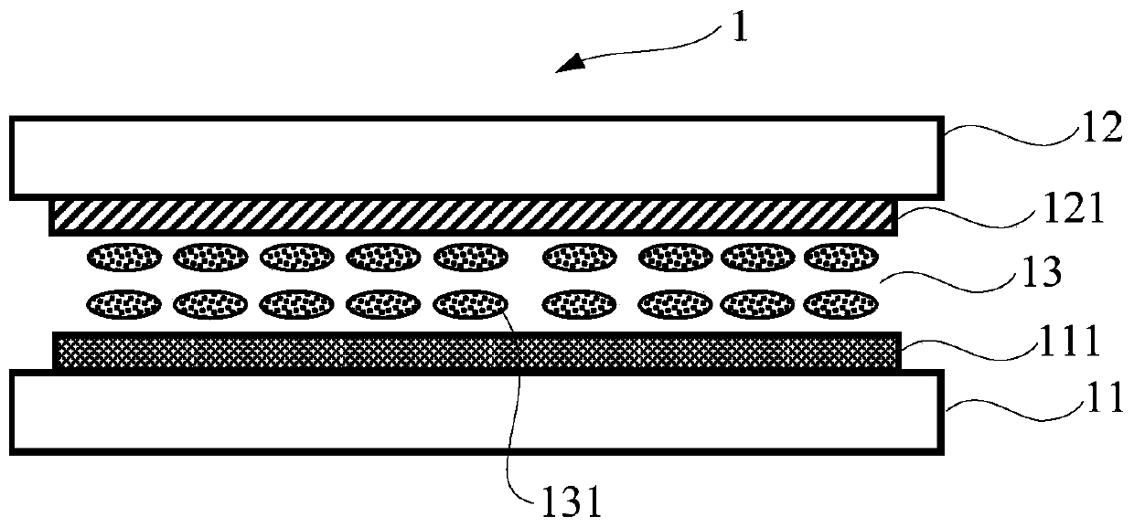
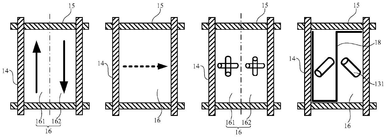
[0051] figure 2 A schematic structural diagram of a display panel provided in Embodiment 1 of the present invention; image 3 An alignment flowchart of a display panel provided in Embodiment 1 of the present invention; Figure 4 Another alignment flow chart of the display panel provided by Embodiment 1 of the present invention; Figure 5a A schematic structural diagram of a pixel unit provided in Embodiment 1 of the present invention; Figure 5b A schematic structural diagram of another pixel unit provided in Embodiment 1 of the present invention; Figure 6 A partial schematic diagram of a pixel area of a display panel provided by Embodiment 1 of the present invention; Figure 7 It is a partial schematic diagram of another pixel region of the display panel provided by Embodiment 1 of the present invention.
[0052] like Figure 2 to Figure 7 As shown, the present embodiment provides a display panel 1, the display panel 1 includes a first substrate 11, a second substrat...
Embodiment 2
[0093] Figure 8 A flow chart of a method for aligning a display panel provided in Embodiment 2 of the present invention; Figure 9 An alignment flow chart of the second substrate provided in Embodiment 2 of the present invention. Such as Figure 8 and Figure 9 As shown, this embodiment provides an alignment method for a display panel, and the alignment method provided by this embodiment is used to align the display panel described in Embodiment 1.
[0094] Wherein, the display panel includes a first substrate and a second substrate oppositely arranged, and a liquid crystal layer arranged between the first substrate and the second substrate. In a specific application, the first substrate is an array substrate, and the second substrate is a color filter substrate; or, the first substrate is a color filter substrate, and the second substrate is an array substrate. I won't repeat them here.
[0095] Such as Figure 8 As shown, specifically, the alignment method includes: ...
Embodiment 3
[0115] This embodiment provides a display device, which includes the display panel described in the first embodiment.
[0116] Wherein, the display panel includes a first substrate and a second substrate oppositely arranged, and a liquid crystal layer arranged between the first substrate and the second substrate. The first substrate is an array substrate and the second substrate is a color filter substrate, or the first substrate is a color filter substrate and the second substrate is an array substrate.
[0117] The side of the first substrate facing the liquid crystal layer is provided with a first alignment layer, and the side of the second substrate facing the liquid crystal layer is provided with a second alignment layer; the first alignment layer is an optical alignment layer, which can align different regions in the pixel unit. The liquid crystal molecules are aligned in different directions, which facilitates the formation of a multi-domain pixel structure; the second ...
PUM
 Abstract
Description
Claims
Application Information
 - R&D
- Intellectual Property
- Life Sciences
- Materials
- Tech Scout
- Unparalleled Data Quality
- Higher Quality Content
- 60% Fewer Hallucinations
Browse by: Latest US Patents, China's latest patents, Technical Efficacy Thesaurus, Application Domain, Technology Topic, Popular Technical Reports.
© 2025 PatSnap. All rights reserved.Legal|Privacy policy|Modern Slavery Act Transparency Statement|Sitemap|About US| Contact US: help@patsnap.com


