
Manufacturing method of imprinting mold

A production method and mold technology, applied in the field of imprinting technology, can solve the problems of low utilization rate, limited products, bursting, etc., and achieve the effects of improving utilization rate and simple preparation process

Pending Publication Date: 2020-07-17
SUZHOU LANPEI OPTOELECTRONICS TECH CO LTD
View PDF0 Cites 3 Cited by
  • Summary
  • Abstract
  • Description
  • Claims
  • Application Information

AI Technical Summary

Problems solved by technology

[0003] In view of the above-mentioned shortcomings of the prior art, the purpose of the present invention is to provide a method for making an embossing mold, which is used to solve the problem that a metal mold in the prior art can produce limited products and low utilization rate; The preparation process of the metal mold is complicated and the cost is high, which is not conducive to mass production; the metal mold generally needs to be covered on the cylinder for embossing work, and multiple metal molds need to be spliced ​​on the periphery of the cylinder, so that the adjacent metal molds There will be a stitching seam between them, and the position of the stitching seam is metal on both sides. When using tape to bond the metal molds on both sides of the stitching seam, the stress is very large. It is easy to cause bursting, which leads to the scrapping of metal molds and other problems

Method used


Image

  • Manufacturing method of imprinting mold
  • Manufacturing method of imprinting mold
  • Manufacturing method of imprinting mold

Examples


Embodiment Construction

[0056] The implementation of the present invention will be illustrated by specific specific examples below, and those skilled in the art can easily understand other advantages and effects of the present invention from the contents disclosed in this specification.

[0057] see Figure 1 to Figure 26 . It should be noted that the structures, proportions, sizes, etc. shown in the drawings attached to this specification are only used to match the content disclosed in the specification, for those who are familiar with this technology to understand and read, and are not used to limit the implementation of the present invention. Limiting conditions, so there is no technical substantive meaning, any modification of structure, change of proportional relationship or adjustment of size, without affecting the effect and purpose of the present invention, should still fall within the scope of the present invention. The disclosed technical content must be within the scope covered. At the s...


PUM

PropertyMeasurementUnit
Widthaaaaaaaaaa
Depthaaaaaaaaaa
Heightaaaaaaaaaa

Abstract

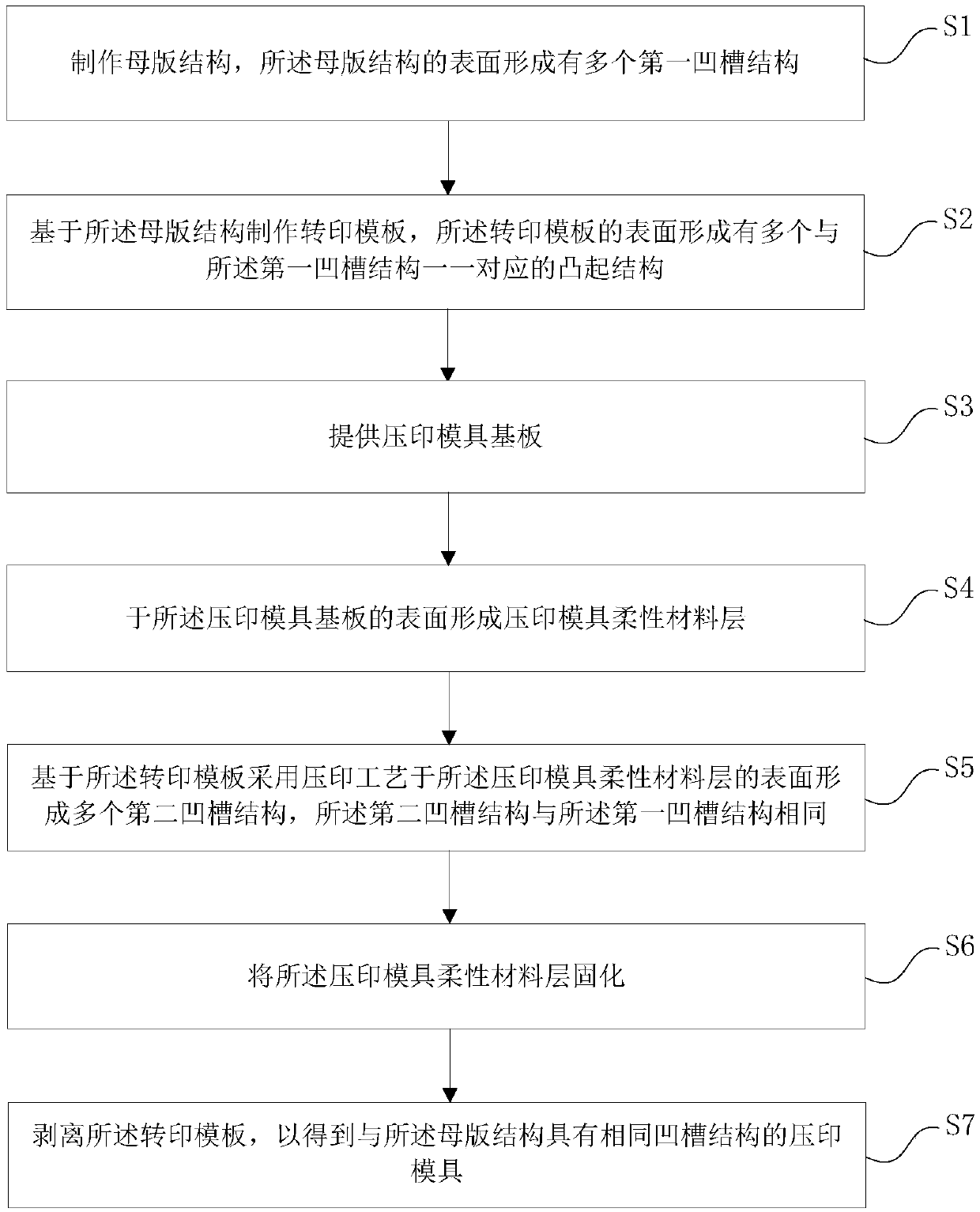
The invention provides a manufacturing method of an imprinting mold. The method comprises the following steps of 1) manufacturing a mother set structure, and forming a plurality of first groove structures on the surface of the mother set structure; 2) manufacturing a transfer printing template based on the mother set structure, wherein a plurality of convex structures are formed on the surface ofthe transfer printing template; 3) providing an imprinting mold substrate; 4) forming an imprinting mold flexible material layer on the surface of the imprinting mold substrate; 5) forming a pluralityof second groove structures on the surface of the flexible material layer of the imprinting mold by adopting an imprinting process based on the transfer template; 6) curing the imprinting mold flexible material layer; 7) peeling the transfer template. According to the manufacturing method of the imprinting mold, the utilization rate of the mother set structure can be increased, the manufacturingprocess is simple, the stress in the imprinting mold is smaller, and the risk of bursting does not exist.

Description

technical field [0001] The invention belongs to the technical field of embossing technology, and in particular relates to a method for making an embossing mold. Background technique [0002] In the prior art, imprinting generally adopts a hard mold, and the imprinting mold is generally a metal mold, such as a typical nickel (Ni) mold. However, metal molds have the following problems: first, metal molds have a lifetime, and must be scrapped if they are defective. The imprinted products that can be produced by a metal mold are limited, and the utilization rate is low; second, the manufacturing process of metal molds It is complicated and costly, which is not conducive to mass production; third, metal molds generally need to be covered on the cylinder for embossing operations, and multiple metal molds need to be spliced ​​on the periphery of the cylinder, so that the adjacent metal molds There will be a splicing seam, and since both sides of the splicing seam are metal, when u...

Claims


Application Information

Patent Timeline
IPC IPC(8): G03F7/00
CPCG03F7/0002G03F7/0017
Inventor 谢自民王亚平平财明林涛
Owner SUZHOU LANPEI OPTOELECTRONICS TECH CO LTD
Learn More