Lamp fault detecting system

A technology for fault detection and lighting, applied in lighting testing, sorting and other directions, can solve the problems of long disassembly and assembly of lamps, labor consumption of workers, cumbersome detection methods, etc., to improve practicability, reliability, and stability. And the effect of firmness and easy collection

Inactive Publication Date: 2020-07-24
CANGZHOU NORMAL UNIV
View PDF10 Cites 2 Cited by
  • Summary
  • Abstract
  • Description
  • Claims
  • Application Information

AI Technical Summary

Problems solved by technology

[0002] As we all know, after the production and processing of lamps, it is usually necessary to energize the inside of the lamp to check whether it can be lit, so as to detect whether the lamp is faulty, and to check the production quality of the lamp. The current power-on detection method is mainly for workers to install the lamp on the lamp holder. , energize the lamp hol

Method used


Image

  • Lamp fault detecting system
  • Lamp fault detecting system
  • Lamp fault detecting system

Examples


Embodiment Construction

[0022] The specific implementation manners of the present invention will be further described in detail below in conjunction with the accompanying drawings and embodiments. The following examples are used to illustrate the present invention, but are not intended to limit the scope of the present invention.

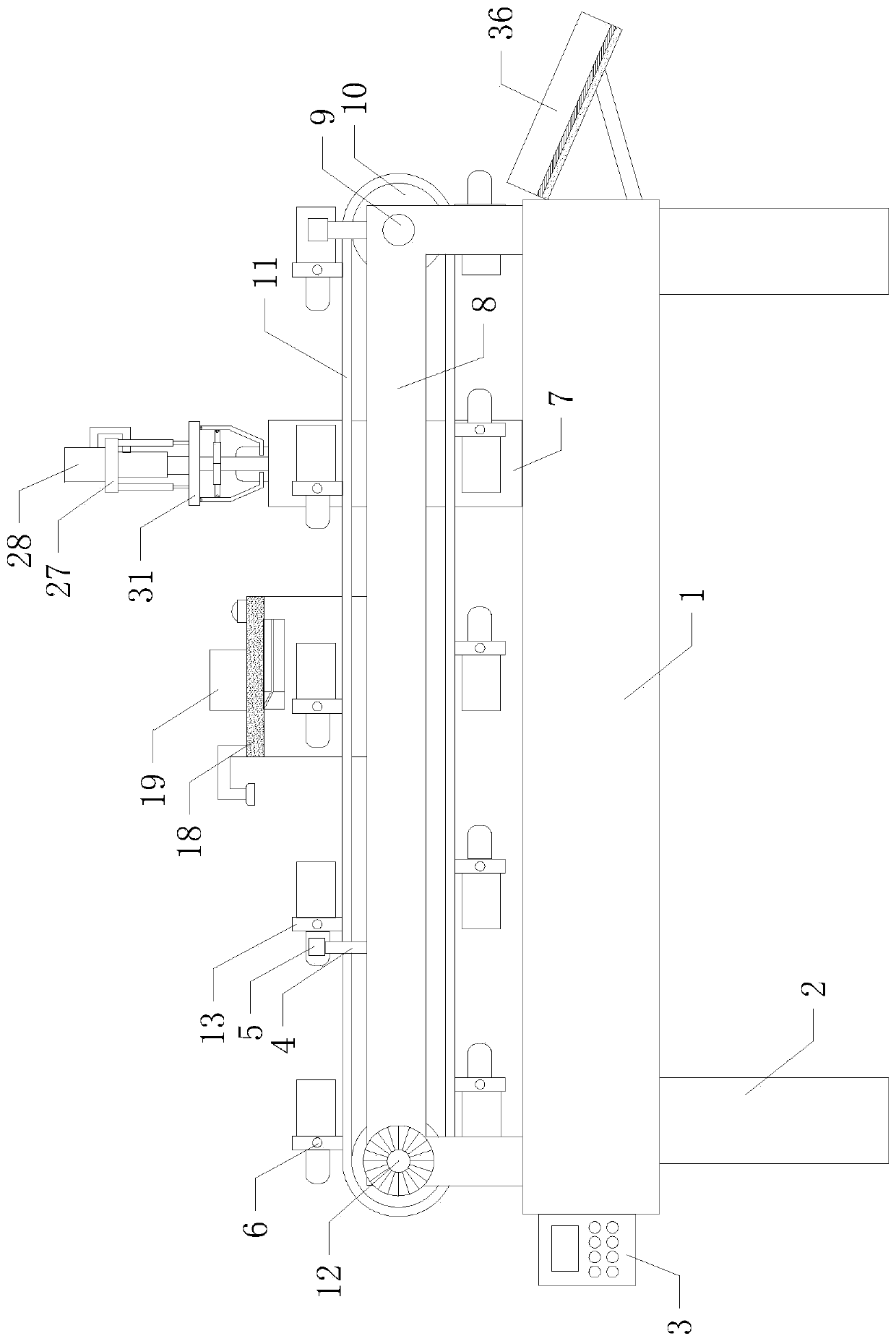
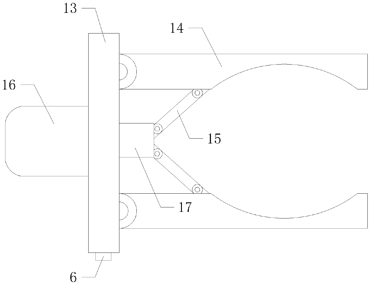
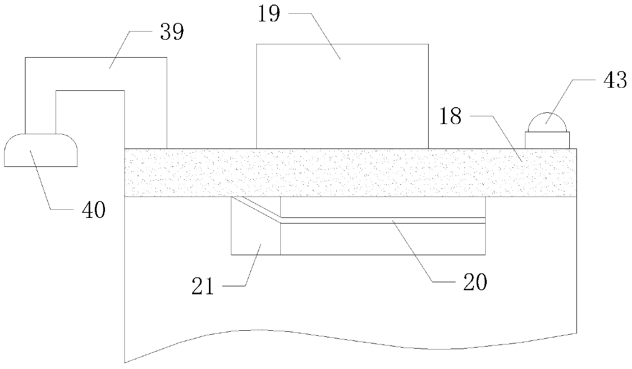
[0023] Such as Figure 1 to Figure 7 As shown, a lamp failure detection system of the present invention, when it is working, open the transmission device, the transmission device drives multiple sets of clamping devices to move, the clamping device at the top of the transmission device transmits to the right, and passes through the external mechanical arm Put the lamps to be detected one by one into the clamping device in the transmission state on the left side of the top of the conveying device, and the clamping device drives the lamps to convey to the right. The first inductor 5 detects the magnetic block 6 on it, and the centralized control box 3 controls the clamping ...


PUM


Abstract

The invention relates to the technical field of detecting devices, in particular to a lamp fault detecting system. By means of automatically monitoring and processing a lamp fault, the lamp fault detecting system can effectively save physical strength for manual detection, simplify the detection manner and improve work efficiency. Meanwhile, workers can be far away from an electrified lamp duringlamp detection, electrical injuries of the workers caused by the electrified lamp can be effectively avoided, and the safety and practicability are improved. The lamp fault detecting system comprisesa workbench, two groups of supporting legs, a centralized control box, two groups of first supports and two groups of first sensors. The two groups of supporting legs are evenly installed on the lowerside of the workbench. The centralized control box is installed at the left end of the workbench. A conveying device is transversely arranged on the front side of the top end of the workbench.

Description

technical field [0001] The invention relates to the technical field of detection equipment, in particular to a detection system for lamp failures. Background technique [0002] As we all know, after the production and processing of lamps, it is usually necessary to energize the inside of the lamp to check whether it can be lit, so as to detect whether the lamp is faulty, and to check the production quality of the lamp. The current power-on detection method is mainly for workers to install the lamp on the lamp holder. , energize the lamp holder and lamp, and then check whether the lamp is on. When using this method of detection, workers need to repeatedly disassemble and assemble the lamp and lamp holder. It takes a long time to install, and the detection efficiency is low. At the same time, the workers are close to the lamps and lamp holders after power-on, which is easy to cause electric injury to the human body. Contents of the invention [0003] In order to solve the a...

Claims


Application Information

Patent Timeline
IPC IPC(8): B07C5/02B07C5/344B07C5/342B07C5/36G01R31/44
CPCB07C5/02B07C5/342B07C5/344B07C5/362G01R31/44
Inventor 于春荣王益芳王新功倪晓红陈寒梅
Owner CANGZHOU NORMAL UNIV
Why Eureka
Try Eureka