Control system of multi-scene adaptation mode automobile cabin
A control system and scene mode technology, applied to vehicle seats, special positions of vehicles, movable seats, etc., can solve problems such as poor user experience, complex structure, and poor reliability, and achieve the goal of improving the sense of luxury and driving experience Effect
- Summary
- Abstract
- Description
- Claims
- Application Information
AI Technical Summary
Problems solved by technology
Method used
Image

Examples
Embodiment Construction
[0060] The specific implementation manner and working principle of the present invention will be further described in detail below in conjunction with the accompanying drawings.
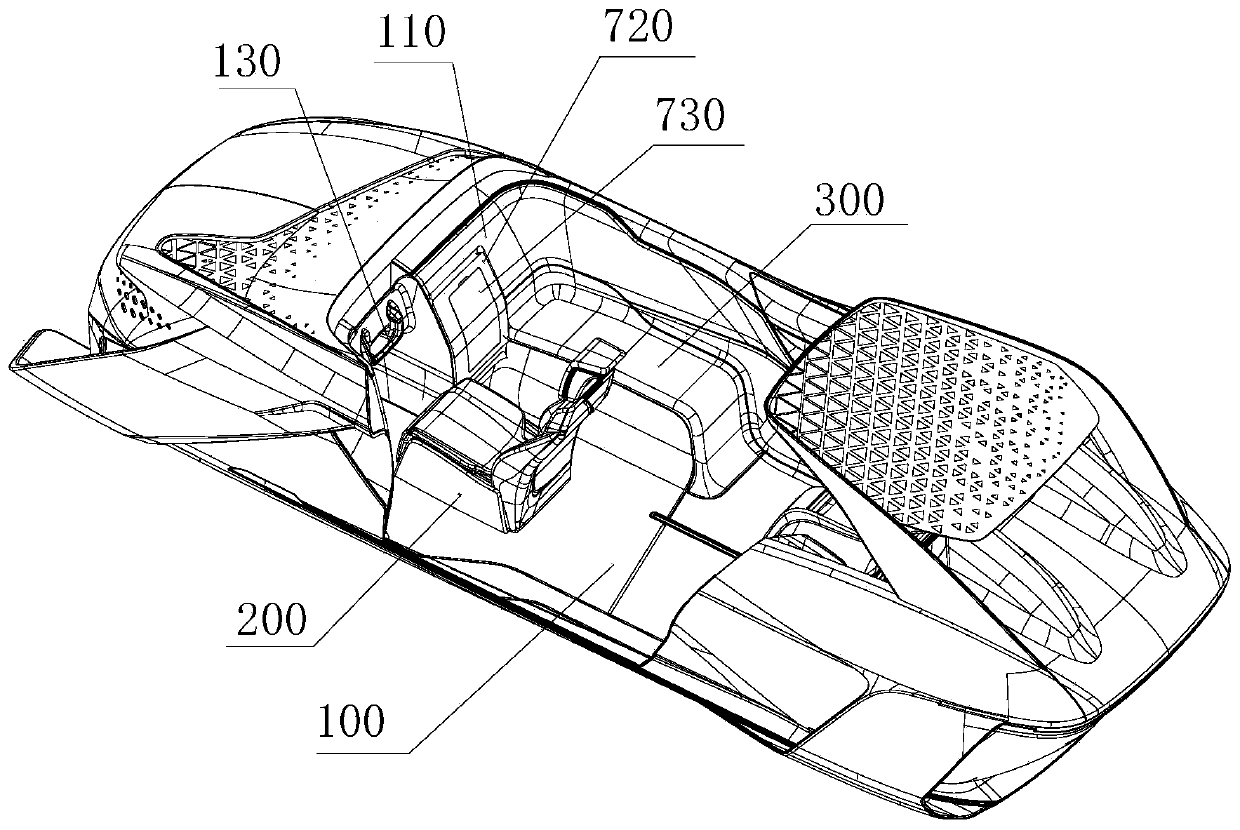
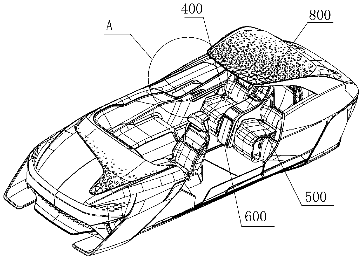
[0061] first reference Figure 1 to Figure 21 The control system of the car cockpit in the multi-scene adaptation mode shown mainly includes a cabin body 1, and the cabin body 1 has at least two scene modes, which can be applicable to use scenarios,
[0062] In this embodiment, N=4, and the scene modes are driving mode, social mode, rest mode and entertainment mode respectively; figure 1 and figure 2 It can be seen that in the driving mode, the arrangement in the cabin body 100; image 3 It can be seen that when it is a social mode, the layout structure in the cabin body 100; Figure 4 It can be seen that for the rest mode, the arrangement in the cabin body 100; Figure 5 It is the arrangement in the entertainment mode cabin body 100 .
[0063] A control system for a car cockpit in a multi-scen...
PUM
 Abstract
Description
Claims
Application Information
PatSnap Eureka turns technology decisions into work you can execute. Powered by our Innovation Knowledge Graph, it runs expert workflows across engineering, life sciences, materials and intellectual property. Get your review-ready output in minutes.


