Unlock instant, AI-driven research and patent intelligence for your innovation.

Clamping device with controllable clamping force and clamping force determination method

A clamping device and clamping force technology, which is applied in the field of optical device chip clamping equipment, can solve the problems of difficult control of clamping force, limited scope of application, and poor versatility, so as to increase the range of changes and save Manual operation, wide range of effects

Pending Publication Date: 2020-07-24
四川华拓光通信股份有限公司
View PDF0 Cites 0 Cited by
  • Summary
  • Abstract
  • Description
  • Claims
  • Application Information

AI Technical Summary

Problems solved by technology

[0002] When moving the chip of an optical device, it is necessary to use a clamping device for clamping. Due to the fragile nature of the chip, it is necessary to precisely control the clamping force of the clamping device; it is difficult to control the clamping force for tiny and fragile items. It is a major problem that plagues the development of high-speed optical devices. The clamping device in the prior art cannot accurately control the clamping force. If the clamping force is too large, the chip will be damaged, and if the clamping force is too small, the chip will be unstable and fall off; In the existing technology, when moving the chip, the suction method is mainly used, and the suction nozzle is equipped with a special size according to different sizes of chips, so the versatility is not strong; and the suction nozzles are all plane adsorption, the scope of use is limited, and it cannot absorb special non-planar structures. Or for objects that are too small in size, when the existing suction method has glue on the bottom of the adsorbed object or hinders its movement, the state of the adsorbed object is easy to change, fall off, and the clamping state is not stable enough; and the use of suction nozzles requires vacuuming equipment , and need to be equipped with suction nozzles of different sizes and calibers, that is, materials, and need to be connected to the air pipe when using it. The cost of the whole system is high, and the use is greatly restricted; a clamping device with a pressure sensor is used, and the mechanical clamping controlled by the pressure sensor feedback The device can solve this problem, but the installation of the pressure sensor requires a certain volume. In the process of clamping small-sized objects, the scope of application is limited due to the complex structure and high cost of the entire system.

Method used


Image

  • Clamping device with controllable clamping force and clamping force determination method
  • Clamping device with controllable clamping force and clamping force determination method
  • Clamping device with controllable clamping force and clamping force determination method

Examples


Embodiment Construction

[0032] The present invention will be further described in detail below in conjunction with the accompanying drawings, so that those skilled in the art can implement it with reference to the description.

[0033] It should be understood that terms such as "having", "comprising" and "including" as used herein do not entail the presence or addition of one or more other elements or combinations thereof.

[0034] Such as Figure 1-7 Shown: a clamping device with controllable clamping force of the present invention, comprising:

[0035] The tail part 1 of the clamping device is provided with a U-shaped groove 101, and the U-shaped groove 101 is provided with a mounting hole 102;

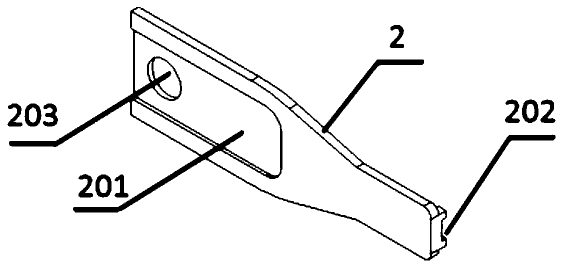
[0036] The tip 2 of the clamping device is provided with a slot 201, the slot 201 is provided with a mounting hole 203; the bridge spring 3 is provided with a mounting hole 302, and one end of the bridge spring 3 is installed on the In the U-shaped groove 101 of the tail part 1 of the clamping device, th...


PUM


Abstract

The invention discloses a clamping device with the controllable clamping force and a clamping force determination method. The clamping device comprises a clamping device tail portion, clamping devicetip ends and bridging leaf springs. U-shaped grooves are formed in the clamping device tail portion, and installation hole positions are arranged in the U-shaped grooves. Insertion grooves are formedin the clamping device tip ends, and installation hole positions are arranged in the insertion grooves. One end of each bridging leaf spring is installed in the corresponding U-shaped groove of the clamping device tail portion, and the other end of each bridging leaf spring is installed in the insertion groove of the corresponding clamping device tip end through a long strip hole. According to theclamping device, the value of the clamping force is adjusted according to the lengths, the thicknesses and the deformation quantities of the bridging leaf springs arranged in the middle, the clampingdevice does not rely on the value of the force applied by the hands of a worker to control the value of the clamping force any longer, the clamping force which is conducted to the clamping device tipends is decided only by the bridging leaf springs, the phenomenon that a clamped chip is destroyed due to the fact that the clamping force is excessively high, or the clamped chip falls off due to the fact that the clamping force is excessively low is avoided, the value of the clamping force can be adjusted through the adjustment of the lengths and the deformation quantities of the bridging leafsprings, and the clamping device is simple in structure, low in cost and high in applicability.

Description

technical field [0001] The invention belongs to the technical field of optical device chip clamping equipment, and more specifically, the invention relates to a clamping device with controllable clamping force and a method for determining the clamping force. Background technique [0002] When moving the chip of an optical device, it is necessary to use a clamping device for clamping. Due to the fragile nature of the chip, it is necessary to precisely control the clamping force of the clamping device; it is difficult to control the clamping force for tiny and fragile items. It is a major problem that plagues the development of high-speed optical devices. The clamping device in the prior art cannot accurately control the clamping force. If the clamping force is too large, the chip will be damaged, and if the clamping force is too small, the chip will be unstable and fall off; In the existing technology, when moving the chip, the suction method is mainly used, and the suction n...

Claims


Application Information

Patent Timeline
Patent Type & Authority Applications(China)
IPC IPC(8): B65G47/90
CPCB65G47/905
Inventor 范巍付贇代海龙
Owner 四川华拓光通信股份有限公司