Driving device and automatic cable take-up and pay-off equipment

A driving device and driving component technology, applied in the field of cable equipment, can solve the problems of motor damage, no power-off braking, etc., and achieve the effects of ensuring stability, preventing overload, and convenient operation

Inactive Publication Date: 2020-07-24
ZHENGZHOU UNIV +1
View PDF9 Cites 1 Cited by
  • Summary
  • Abstract
  • Description
  • Claims
  • Application Information

AI Technical Summary

Problems solved by technology

[0004] The device for automatically retracting and unwinding cables in the above-mentioned patent documents will cause damage to the motor when there is overload in the winding and unwinding; the braking device only has the function of rapid braking, and does not have the function of power-off braking.

Method used


Image

  • Driving device and automatic cable take-up and pay-off equipment
  • Driving device and automatic cable take-up and pay-off equipment
  • Driving device and automatic cable take-up and pay-off equipment

Examples


Embodiment Construction

[0026] The following will clearly and completely describe the technical solutions in the embodiments of the present invention with reference to the accompanying drawings in the embodiments of the present invention. Obviously, the described embodiments are only part of the embodiments of the present invention, not all of them. Based on the embodiments of the present invention, all other embodiments obtained by persons of ordinary skill in the art without creative efforts fall within the protection scope of the present invention.

[0027] It should be noted that all directional indications in the embodiments of the present invention, such as up, down, left, right, front, back... are only used to explain the relative positional relationship between the components in a certain posture as shown in the drawings, Sports conditions, etc., if the specific posture changes, the directional indication will also change accordingly.

[0028] In the present invention, unless otherwise specif...


PUM


Abstract

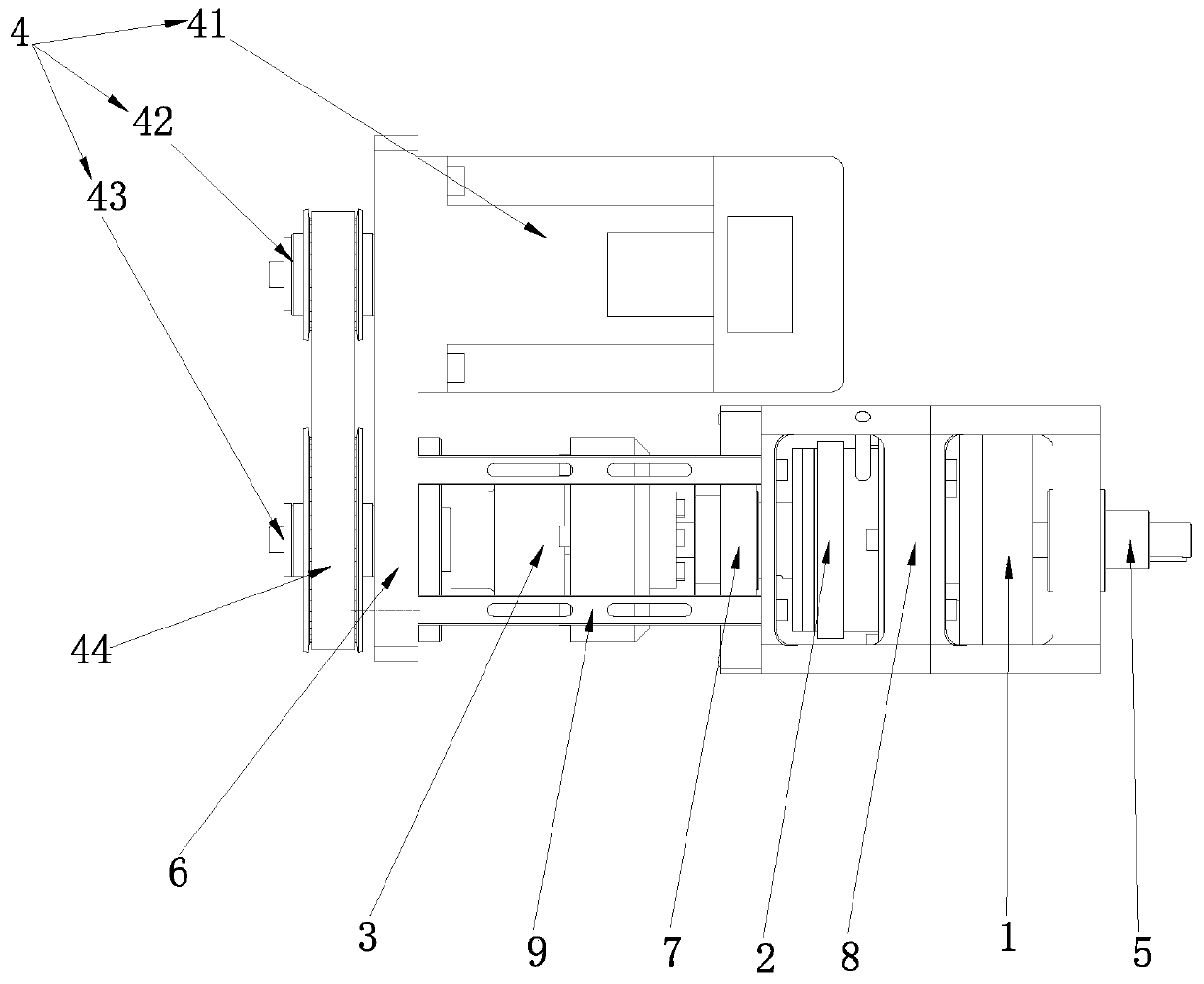
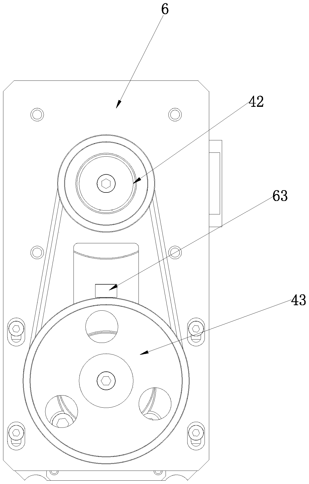
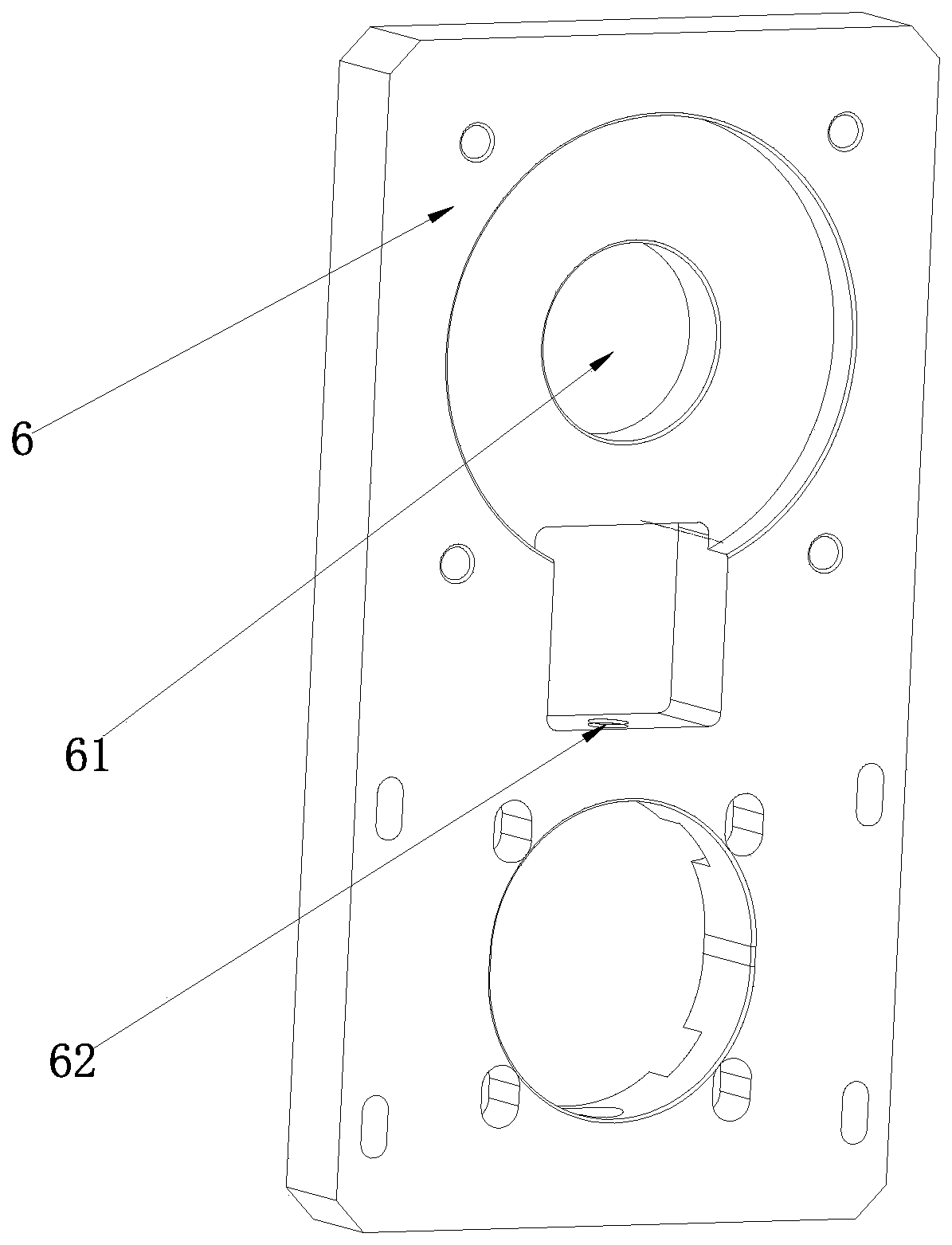
The invention discloses a driving device and automatic cable take-up and pay-off equipment. The driving device comprises an electromagnetic brake, a clutch, a torque limiter and a driving assembly capable of rotating forwards and reversely, wherein the torque limiter is in transmission connection with the driving assembly; the clutch is in transmission connection with the torque limiter; an outputshaft is arranged on the electromagnetic brake in a transmission mode; and the output shaft is in transmission connection with the clutch. When overload occurs, the driving assembly can be protected;the electromagnetic brake has a function of power-off braking and ensures that a take-up device does not rotate at will; and a variety of control modes can be achieved through the clutch. The drivingdevice and the automatic cable take-up and pay-off equipment are applicable to the field of cable equipment.

Description

technical field [0001] The invention relates to the field of cable equipment, in particular to a driving device and automatic retractable cable equipment. Background technique [0002] With the continuous development of robot technology, robots are used more and more in people's work and life. There are two main forms of robot power, one is driven by its own battery, and the working time is limited, and the other is that the robot supplies power to the robot through a cable, and the robot drags the cable to move and work. There are also two remote control methods for robots, one is wireless communication remote control, and the other is wired communication control. Wired power supply and wired communication control require the cable to follow the movement of the robot, the cable can be released as the robot moves forward, and the cable can be retracted as the robot retreats during the return journey of the robot. [0003] The patent document with the application number CN1...

Claims


Application Information

Patent Timeline
IPC IPC(8): B65H75/38B65H75/44
CPCB65H75/38B65H75/4428B65H75/4486B65H2701/34
Inventor 方宏远赵鹏李斌雷建伟郭成超潘艳辉李海军吴伟卢宗胜
Owner ZHENGZHOU UNIV
Why Eureka
Try Eureka