
Centrifugal supergravity casting and directional solidification system

A technology of directional solidification and supergravity, which is applied in the field of centrifugal supergravity casting and directional solidification devices, and supergravity material preparation devices. It can solve the problems that the melting and casting system has no heating function, performance testing cannot be performed, and the solidification process is not controlled.

Pending Publication Date: 2020-07-24
ZHEJIANG UNIV
View PDF6 Cites 4 Cited by
  • Summary
  • Abstract
  • Description
  • Claims
  • Application Information

AI Technical Summary

Problems solved by technology

[0003] However, the melting and casting system of existing high-gravity melting and casting equipment has no heating function, and can only be cooled with the furnace. The solidification process is uncontrolled, and the samples are small, so only composition optimization can be performed, and performance testing cannot be performed. Therefore, composition optimization based on high-gravity technology It is seriously out of touch with performance testing, and it is impossible to realize the preparation of hypergravity materials based on material performance requirements, and because of the nonlinear relationship between material composition-structure-performance, it is difficult to realize the integrated research method of material design and preparation for actual performance requirements

Method used


Image

  • Centrifugal supergravity casting and directional solidification system
  • Centrifugal supergravity casting and directional solidification system
  • Centrifugal supergravity casting and directional solidification system

Examples


Embodiment Construction

[0078] The present invention will be further described below in conjunction with the accompanying drawings and specific implementation.

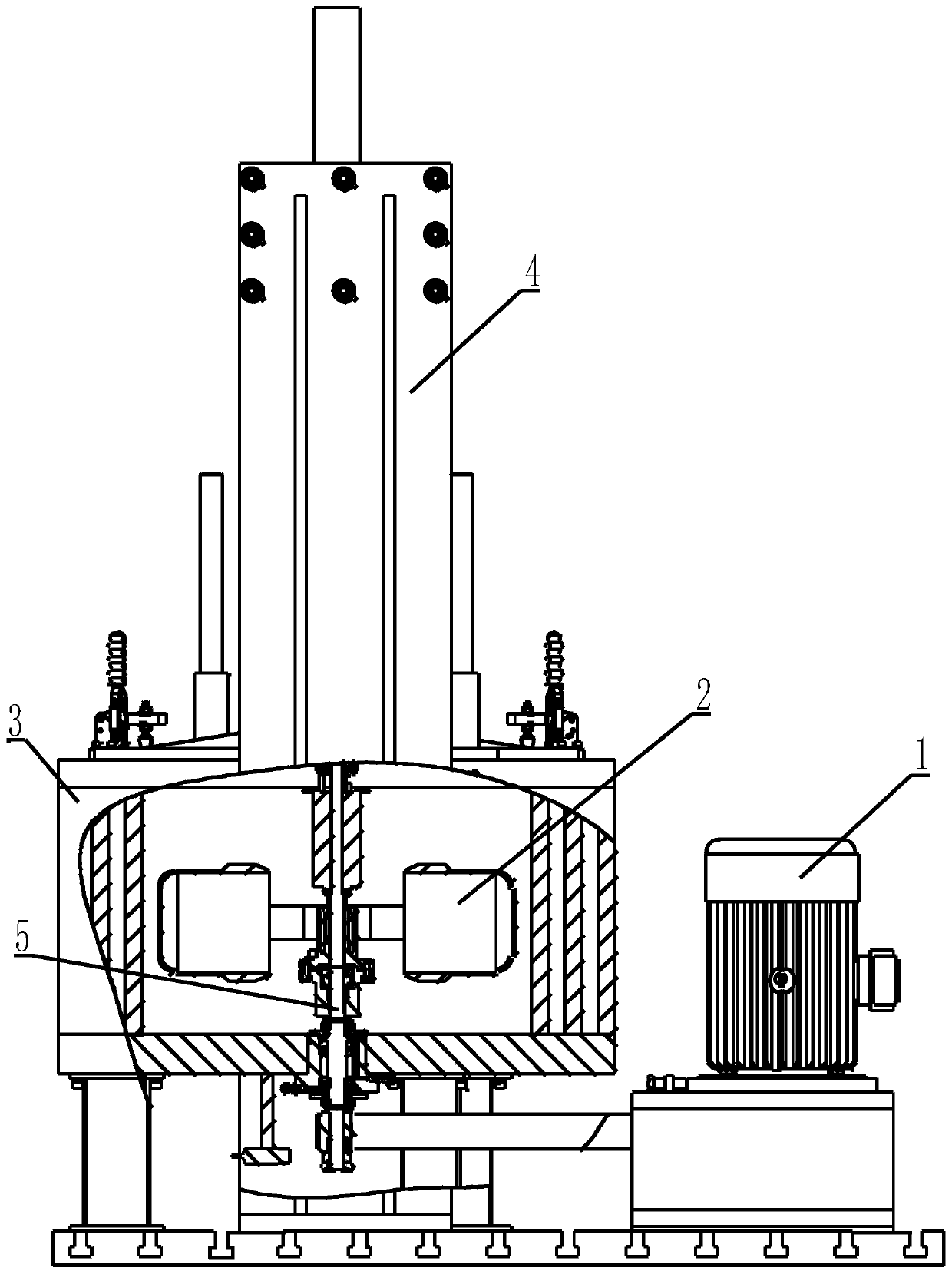
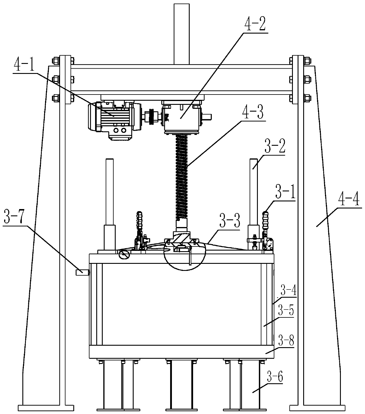
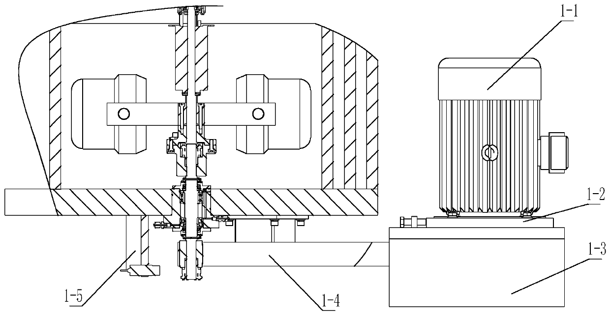
[0079] Such as figure 1 As shown, the specific implementation of the entire device includes a centrifugal host 1, a rotor system 2, an experimental chamber 3, a lifting system 4, and a down-driven spindle complex 5; the rotor system 2 and the down-driven spindle complex 5 are installed in the experimental chamber 3 , the bottom of the experimental chamber 3 is installed on the device base through a buffer structure, the centrifugal host 1 is installed on the device base at the side of the experimental chamber 3 and connected to the lower end of the down-driving spindle complex 5, and the upper end of the down-driving spindle complex 5 is connected to the rotor system 2, the lifting system 4 is installed on the base of the device and located above the experimental chamber 3, and the lifting system 4 is connected to the chamber cover of the ex...


PUM


Abstract

The invention discloses a centrifugal supergravity casting and directional solidification system. A rotor system and a lower drive type main shaft complex are installed in an experiment cavity, the bottom of the experiment cavity is installed on the device base in a buffering mode, a centrifugal main machine is installed on the experiment cavity and connected with the lower drive type main shaft complex, the lower drive type main shaft complex is connected with the rotor system, and a lifting system is located above the experiment cavity and connected with the experiment cavity cover. A directional casting system is arranged in a hanging cup, a heat preservation device is arranged in the hanging cup, a heating device is arranged in the heat preservation device, a crucible device is arranged in the heating device, and the hanging cup is hung at the end of the rotating arm of the supergravity centrifugal machine through lifting lugs on the two sides in a hinged mode. The supergravity directional solidification function is achieved through a power reduction method in the centrifugal supergravity environment by carrying the high-temperature melting and casting furnace or the directional melting and casting furnace, the key problem that the temperature gradient is difficult to control in the supergravity directional solidification process is solved, operation is convenient, and safety and reliability are achieved.

Description

technical field [0001] The invention relates to a high-gravity material preparation device in the technical field of material preparation and directional solidification, in particular to a centrifugal high-gravity casting and directional solidification device. Background technique [0002] Usually, in order to improve the comprehensive mechanical properties of the alloy, two ways are adopted: one is to add a large amount of alloying elements, and through a reasonable heat treatment process to produce solid solution strengthening, precipitation strengthening and grain boundary strengthening, etc., so as to ensure that the alloy has properties from room temperature to Good strength at high temperature, indicating stability and good plasticity; the second is to start with the solidification process and adopt the directional solidification process to prepare the columnar grain structure with grain boundaries parallel to the principal stress axis to eliminate harmful transverse gr...

Claims


Application Information

Patent Timeline
IPC IPC(8): C30B11/00C30B29/52C30B30/00
CPCC30B11/00C30B11/008C30B11/006C30B29/52C30B30/00
Inventor 韦华张泽陈云敏林伟岸
Owner ZHEJIANG UNIV
Learn More