Heat pump control method, device and system, storage medium and related equipment
A control method and technology of an electric heating device, applied in the field of heat pumps, can solve the problems of poor anti-freezing effect, low accuracy of anti-freezing control method, large power consumption, etc., and achieve the effect of solving low accuracy and improving anti-freezing efficiency.
- Summary
- Abstract
- Description
- Claims
- Application Information
AI Technical Summary
Problems solved by technology
Method used
Image
Examples
Embodiment 1
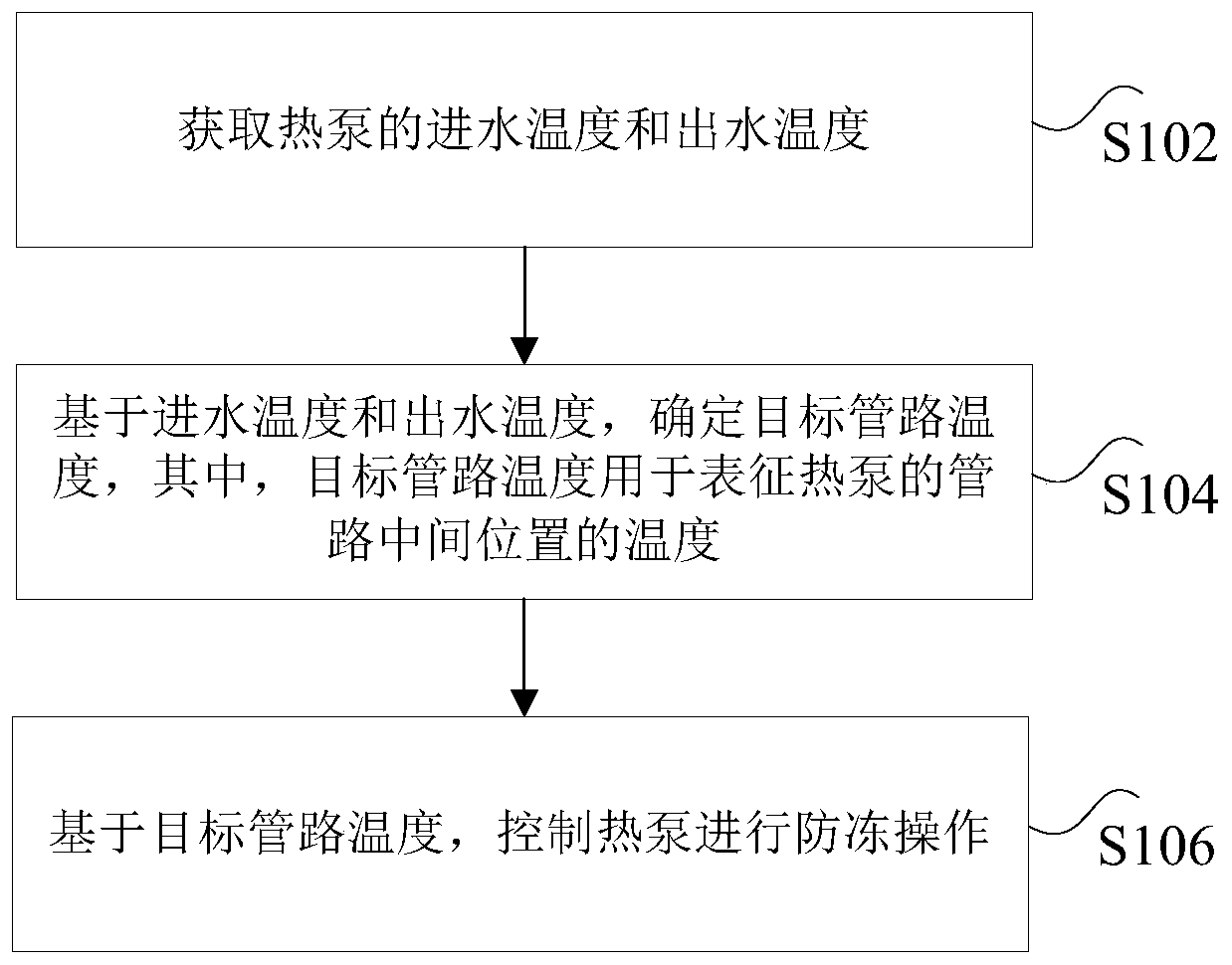
[0030] An embodiment of the present application provides a method for controlling a heat pump, and the method is applied to a heat pump unit.
[0031] Combine below figure 1 The heat pump control method provided in the embodiment of the present application is introduced in detail. Such as figure 1 As shown, the method includes the following steps:
[0032] Step S102, obtaining the inlet water temperature and outlet water temperature of the heat pump;
[0033] In the embodiment of the present application, the inlet water temperature and the outlet water temperature can be collected by thermocouples deployed at the water inlet and outlet of the heat pump, wherein the temperature collected by the thermocouple deployed at the water inlet of the heat pump is used as the inlet water temperature , the temperature collected by the thermocouple deployed at the water outlet of the heat pump is taken as the outlet water temperature.
[0034] Step S104, based on the inlet water temper...
Embodiment 2
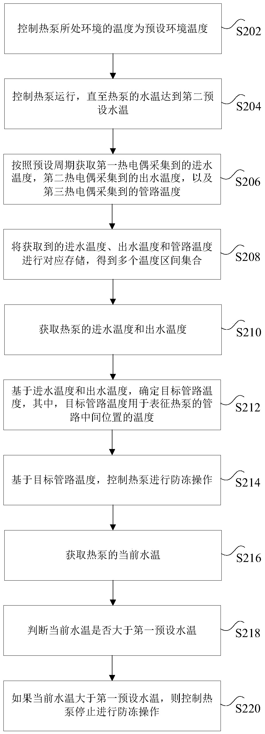
[0042] Such as figure 2 As shown, the method includes the following steps:
[0043] Step S202, controlling the temperature of the environment where the heat pump is located to be the preset ambient temperature;
[0044] In this embodiment, the preset ambient temperature may be a temperature determined according to the actual usage of the heat pump, for example, it may be -10°C or -20°C.
[0045] In an exemplary embodiment of the embodiment of the present application, an experiment may be carried out in an enthalpy difference laboratory to determine the relationship between the inlet water temperature, the outlet water temperature and the pipeline temperature of the heat pump. Specifically, in order to accurately simulate the actual use of the heat pump, the temperature outside the enthalpy difference laboratory can be lowered to about -10°C and -20°C respectively for experiments.
[0046] Step S204, controlling the operation of the heat pump until the water temperature of t...
Embodiment 3
[0068] The method for controlling a heat pump provided in the embodiment of the present application may be applied to a heat pump. In the embodiment of the present application, the whole method can be divided into an experiment flow and a control flow.
[0069] Among them, the experimental process is as follows:
[0070] First, prepare a set of heat pumps outside the enthalpy difference laboratory. The temperature outside is reduced to about -10°C. Turn off the machine at about ℃, when the water temperature drops, the machine will not turn on automatically, and then start to record the temperature at this time t=50, and then record the temperature of the water in and out and the corresponding thermocouple temperature every hour, and record the temperature of the three thermocouples 6 ℃, 4°C, 2°C and the corresponding inlet and outlet water temperatures, record 3 groups, the outlet water temperature is t 出水1 , t 出水2 , t 出水3 , the corresponding three temperatures of the inco...
PUM
 Abstract
Description
Claims
Application Information
 - R&D
- Intellectual Property
- Life Sciences
- Materials
- Tech Scout
- Unparalleled Data Quality
- Higher Quality Content
- 60% Fewer Hallucinations
Browse by: Latest US Patents, China's latest patents, Technical Efficacy Thesaurus, Application Domain, Technology Topic, Popular Technical Reports.
© 2025 PatSnap. All rights reserved.Legal|Privacy policy|Modern Slavery Act Transparency Statement|Sitemap|About US| Contact US: help@patsnap.com


