Loose rock-soil layer grouting test device and method
A technology of grouting test and rock-soil layer, applied in the direction of measuring devices, diffusion analysis, instruments, etc., can solve the quantitative influence law of grouting effect, can not realize the simulation of loose formation grouting reinforcement process, grout penetration law and reinforcement evaluation effect and the monitoring of the grout diffusion range, the inability to truly simulate the grouting process, etc., to achieve the effects of ensuring accuracy and controllability, optimizing grouting process parameters, and ensuring sealing
Pending Publication Date: 2020-07-24
HEBEI UNIVERSITY
View PDF0 Cites 1 Cited by
- Summary
- Abstract
- Description
- Claims
- Application Information
AI Technical Summary
Problems solved by technology
[0006] One of the purposes of the present invention is to provide a loose rock soil layer grouting test device to solve the problem that the current test equipment cannot truly simulate the grouting process and the quantitative influence of pump pressure parameters on the grouting effect
[0007] The second object of the present invention is to provide a kind of te
Method used
View moreImage
Smart ImageViewing Examples
Examples
 PUM
 Abstract
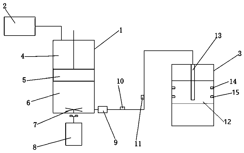
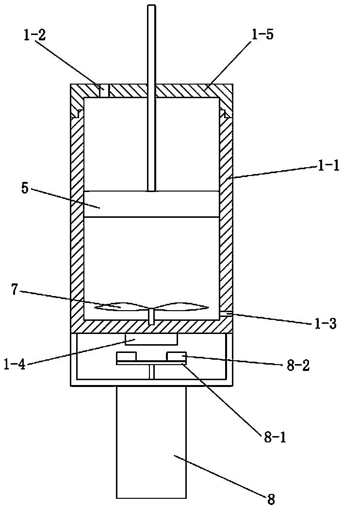
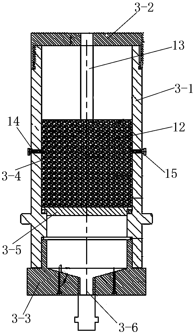
The invention relates to a loose rock-soil layer grouting test device and method. The device comprises a piston stirring slurry storage container, a pressurizing piston is arranged in a shell of the piston stirring slurry storage container, an inner cavity of the piston stirring slurry storage container is divided into a pressurizing driving cavity and a slurry storage cavity by the pressurizing piston, the pressurizing driving cavity communicates with a constant-speed constant-pressure constant-flux pump through a pipeline, the constant-speed constant-pressure constant-flux pump is used for inputting a liquid into the pressurizing driving cavity, an electromagnetic stirring mechanism is arranged at one end of a slurry storage cavity of the piston stirring slurry storage container, and theslurry storage cavity communicates with a grouting simulation test kettle through a pipeline. According to the method, the device is used for carrying out a grouting test on the simulated soil layer.The device is simple in structure, stable in work, convenient to operate, safe, reliable, resistant to high pressure and capable of truly simulating the grouting process and the quantitative influence rule of pump pressure parameters on the grouting effect.
Description
technical field [0001] The invention relates to a soil layer seepage grouting effect evaluation test device, in particular to a loose rock soil layer grouting test device and method. Background technique [0002] At present, with the rapid development of our country's economy, more and more geotechnical engineering constructions are being carried out in the accumulation, alluvial or sedimentary strata of mountains and river bank slopes, edges and terraces, and loose strata with different thicknesses are often encountered. Most of these unconsolidated or weakly cemented sand and pebble formations are in a loose state with poor cementation and strong instability. Therefore, when the above-mentioned loose stratum is used as the bearing stratum of the foundation and during the excavation of the subway foundation pit, large stratum deformation may be caused, which will have adverse effects and cause accidents, resulting in casualties. Therefore, the above-mentioned loose formati...
Claims
Login to View More Application Information
Patent Timeline
 IPC IPC(8): G01N13/04G01N15/08
CPCG01N13/04G01N15/0806G01N15/0826G01N2013/003
Inventor 余莉程旷
Owner HEBEI UNIVERSITY
Features
- R&D
- Intellectual Property
- Life Sciences
- Materials
- Tech Scout
- Unparalleled Data Quality
- Higher Quality Content
- 60% Fewer Hallucinations
Learn More Browse by: Latest US Patents, China's latest patents, Technical Efficacy Thesaurus, Application Domain, Technology Topic, Popular Technical Reports.
© 2025 PatSnap. All rights reserved.Legal|Privacy policy|Modern Slavery Act Transparency Statement|Sitemap|About US| Contact US: help@patsnap.com


