A calibration device and method based on multi-laser ranging

A calibration method and calibration point technology, which is applied in the directions of measuring distance, measuring device, line-of-sight measurement, etc., can solve the problems of angle insensitivity, camera position setting error, and difficulty in accurately determining the angle, so as to improve synthesis accuracy and improve synthesis Speed, the effect of improving adaptability

Active Publication Date: 2021-03-23
天目爱视(北京)科技有限公司
View PDF4 Cites 0 Cited by
  • Summary
  • Abstract
  • Description
  • Claims
  • Application Information

AI Technical Summary

Problems solved by technology

However, in practical applications, it is found that unless there is an accurate angle measurement device, the user is not sensitive to the angle, and it is difficult to determine the angle accurately; the size of the target object is difficult to accurately determine, such as the scene constructed by the 3D model of the above-mentioned riverside house
And the measurement error leads to the camera position setting error, which will affect the acquisition and synthesis speed and effect; the accuracy and speed need to be further improved

Method used


Image

  • A calibration device and method based on multi-laser ranging
  • A calibration device and method based on multi-laser ranging
  • A calibration device and method based on multi-laser ranging

Examples


Embodiment Construction

[0038] Exemplary embodiments of the present disclosure will be described in more detail below with reference to the accompanying drawings. Although exemplary embodiments of the present disclosure are shown in the drawings, it should be understood that the present disclosure may be embodied in various forms and should not be limited by the embodiments set forth herein. Rather, these embodiments are provided for more thorough understanding of the present disclosure and to fully convey the scope of the present disclosure to those skilled in the art.

[0039] 3D Acquisition Calibration Process

[0040] When the target object to be collected is B, the calibration object A can be placed around the B at this time, but in many cases the calibration object A cannot be placed near the target object B. At this point you can:

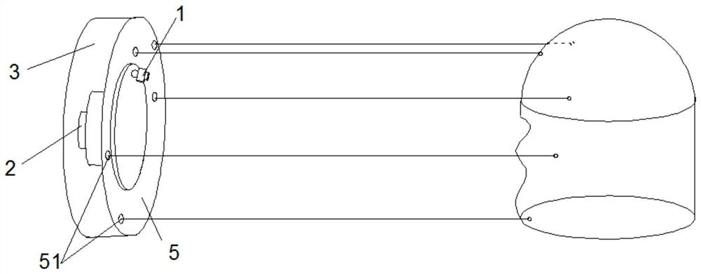
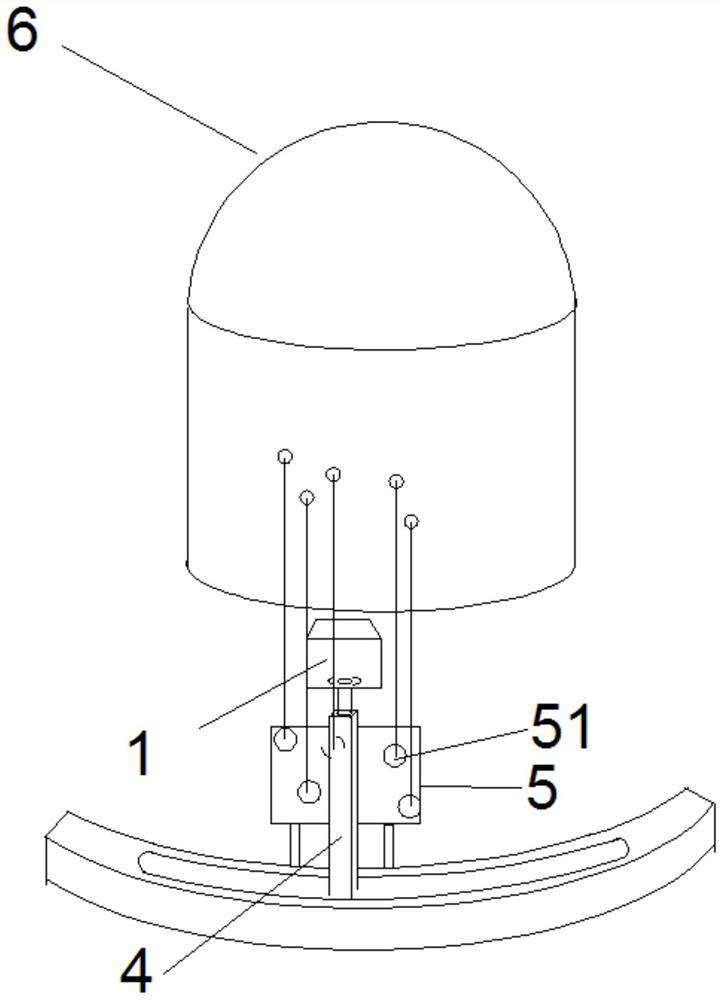
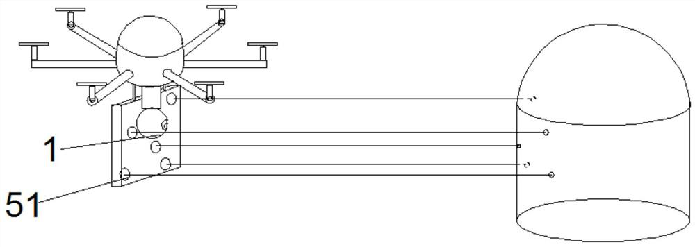
[0041] 1. Use the calibration device to emit laser light towards the target to form multiple calibration point spots, and obtain the coordinates of the calibra...


PUM


Abstract

The embodiment of the present invention provides a calibration device and method in 3D modeling, (1) using the calibration device to project multiple parallel light beams to the target, and forming multiple light spots on the surface of the target, which are calibration points; The positional relationship between the beams determines the x-coordinate and y-coordinate of the calibration point; (2) measures the distance between each spot and the exit plane, thereby determining the z-coordinate of the corresponding calibration point; (3) uses the image acquisition device to collect the target object A plurality of images, wherein at least some of the images include the plurality of light spots; (4) marking the coordinates of the target object according to the coordinates of the multiple marking points. The absolute size calibration of the target object is realized by the method of multiple laser range finders.

Description

technical field [0001] The invention relates to the technical field of shape measurement, in particular to the technical field of 3D shape measurement. Background technique [0002] At present, when using a visual method for 3D acquisition and measurement, the camera is usually rotated relative to the target object, or multiple cameras are set around the target object for simultaneous acquisition. For example, the Digital Emily project of the University of Southern California uses a spherical bracket, and hundreds of cameras are fixed at different positions and angles on the bracket, so as to realize 3D acquisition and modeling of the human body. However, in either way, the distance between the camera and the target object needs to be short, at least within the range that can be arranged, so that the camera can collect images of the target object at different positions. [0003] However, in some applications, it is not possible to collect images around the target object. F...

Claims


Application Information

Patent Timeline
Patent Type & Authority Patents(China)
IPC IPC(8): G06T7/80G06T7/521G01C25/00G01C3/00
CPCG01C3/00G01C25/00G06T2207/10028G06T7/521G06T7/85
Inventor 左忠斌左达宇
Owner 天目爱视(北京)科技有限公司
Why Eureka
Try Eureka