

Medium-voltage self-opening vacuum circuit breaker
A vacuum circuit breaker and self-dividing technology, applied in high-voltage air circuit breakers, circuits, and high-voltage/high-current switches, etc., can solve problems such as abnormal action of vacuum circuit breakers, and achieve the effect of shortening fault time, avoiding abnormal action, and quickly cutting off
Pending Publication Date: 2020-07-24
王炎
View PDF0 Cites 0 Cited by
- Summary
- Abstract
- Description
- Claims
- Application Information
AI Technical Summary
Problems solved by technology
[0003] However, when the energy storage element and action controller in the vacuum circuit breaker fail, it is very easy to
Method used
View moreImage
Smart ImageViewing Examples

Examples
 PUM
 Abstract
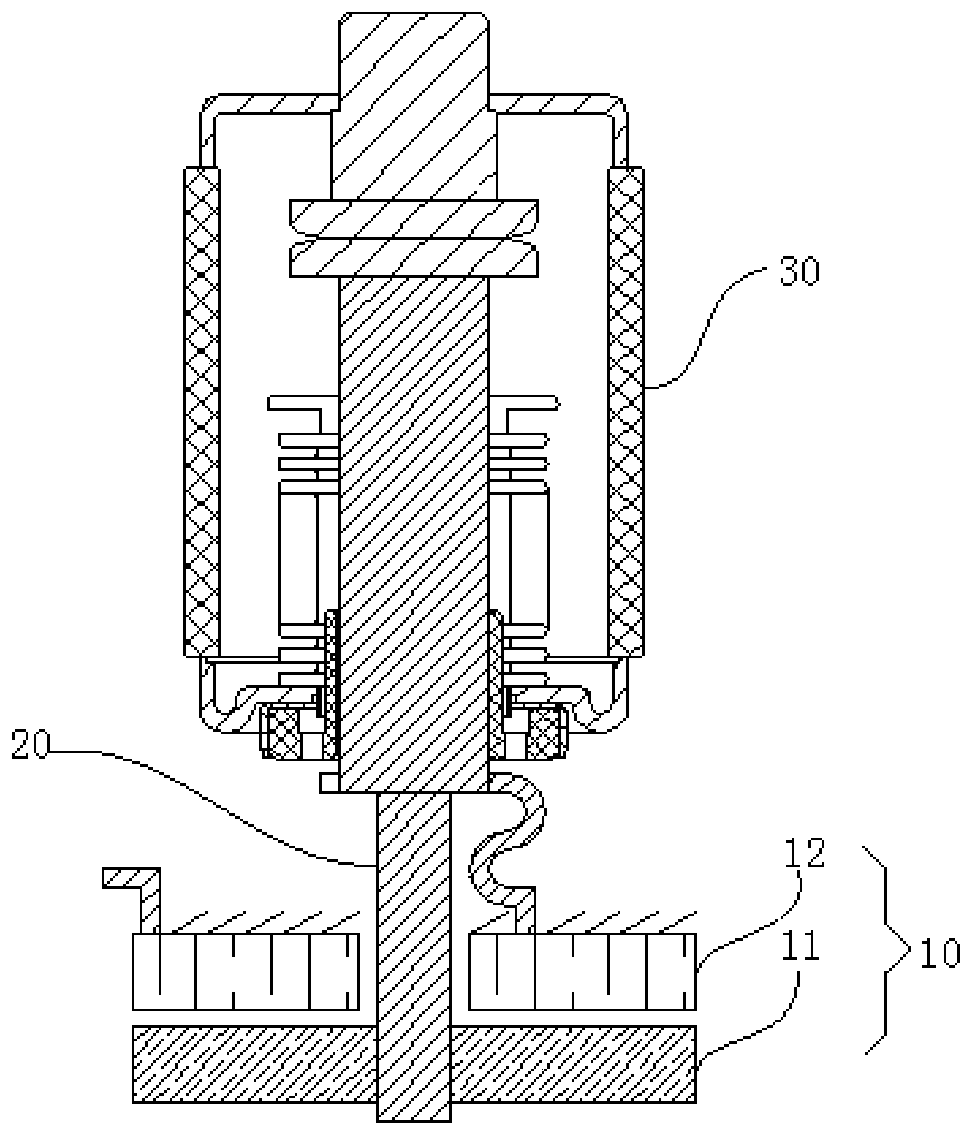
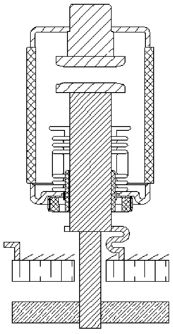
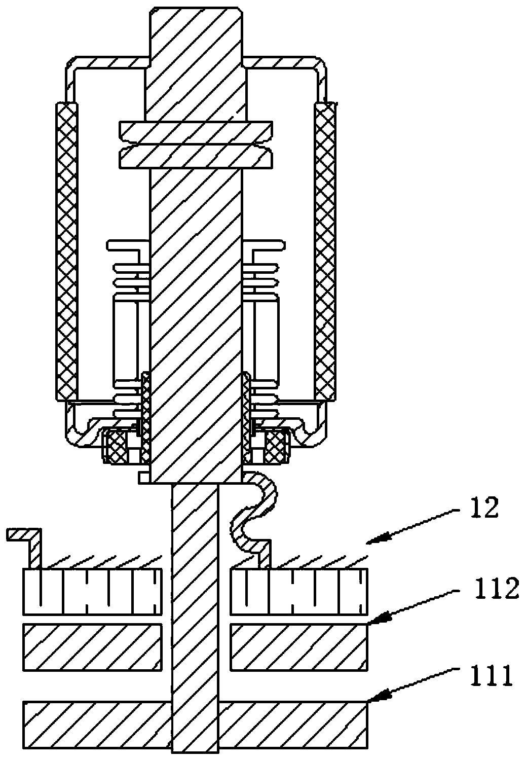
The invention discloses a medium-voltage self-opening vacuum circuit breaker and belongs to the technical field of vacuum circuit breakers. The circuit breaker comprises a shell, a driving system, a transmission mechanism and a vacuum arc-extinguishing chamber, wherein the driving system, the transmission mechanism, and the vacuum arc-extinguishing chamber are installed in the shell, and the vacuum arc-extinguishing chamber is used for switching off/ on a load side fault current. The driving system comprises a moving body element and a static body element which are used for forming an interacted electromagnetic force in a matched mode, a static contact and a moving contact located under the static contact are fixedly arranged in the vacuum arc-extinguishing chamber, the static body elementis fixedly connected with an inner wall of the shell, a wire inlet end of the static body element is connected with the moving contact through flexible connection, and a wire outlet end is connectedwith a load; and the static contact is connected to a power grid, and the moving body element is connected with the moving contact through a transmission mechanism so as to drive the moving contact and the static contact of the vacuum arc-extinguishing chamber to be opened by utilizing an electromagnetic force between the moving body element and the static body element. According to the vacuum circuit breaker disclosed by the invention, an energy storage element, a measurement and control instrument and other structures are omitted so that the circuit breaker is simple in structure and high inreliability.
Description
technical field [0001] The invention relates to the technical field of vacuum circuit breakers, in particular to a medium-voltage self-opening vacuum circuit breaker. Background technique [0002] "Vacuum circuit breaker" is named because the arc extinguishing medium and the insulating medium of the contact gap after arc extinguishing are both high vacuum. It has the advantages of small size, light weight, suitable for frequent operation, and no maintenance for arc extinguishing. It is widely used in power grid. Vacuum circuit breaker is an indoor power distribution device in 3-35kV, 50Hz three-phase AC system. It can be used for protection and control of electrical equipment in industrial and mining enterprises, power plants, and substations. It is especially suitable for oil-free, less In places where maintenance and frequent operations are used, circuit breakers can be configured in central cabinets, double-layer cabinets, and fixed cabinets to control and protect high-v...
Claims
Login to View More Application Information
Patent Timeline
 IPC IPC(8): H01H33/666H01H33/664
CPCH01H33/664H01H33/666
Inventor王炎
Owner王炎