
A Multi-order Acoustic Orbital Angular Momentum Transmitting Transducer Array

A technology for transmitting transducers and orbital angular momentum, applied in transmission systems, electrical components, etc., can solve problems such as carrier frequency limitation, low transmission capacity, and transmission rate that cannot meet information transmission, so as to simplify demodulation difficulty and improve resolution The effect of simple adjustment of precision, driving mode and multi-stage multiplexing mode

Active Publication Date: 2021-05-28
HARBIN ENG UNIV
View PDF0 Cites 0 Cited by
  • Summary
  • Abstract
  • Description
  • Claims
  • Application Information

AI Technical Summary

Problems solved by technology

[0002] Acoustic waves are currently the best way for underwater long-distance information transmission. However, high-frequency sound waves still have strong attenuation in water media. Although there are methods such as differential phase shift keying and quadrature amplitude modulation to improve the information transmission of underwater acoustic communication rate, but its transmission capability is still limited by the low carrier frequency, coupled with the gradual increase in people's exploration of marine resources, and the gradual increase in the amount of modern underwater data transmission, the existing transmission rate can no longer meet the requirements of information transmission, so , it is necessary to develop a new multiplexing method to expand the spectral efficiency of underwater acoustic communication, thereby increasing the underwater information transmission rate

Method used


Image

  • A Multi-order Acoustic Orbital Angular Momentum Transmitting Transducer Array
  • A Multi-order Acoustic Orbital Angular Momentum Transmitting Transducer Array
  • A Multi-order Acoustic Orbital Angular Momentum Transmitting Transducer Array

Examples


Embodiment Construction

[0026] The technical solutions in the embodiments of the present invention will be clearly and completely described below in conjunction with the drawings in the embodiments of the present invention.

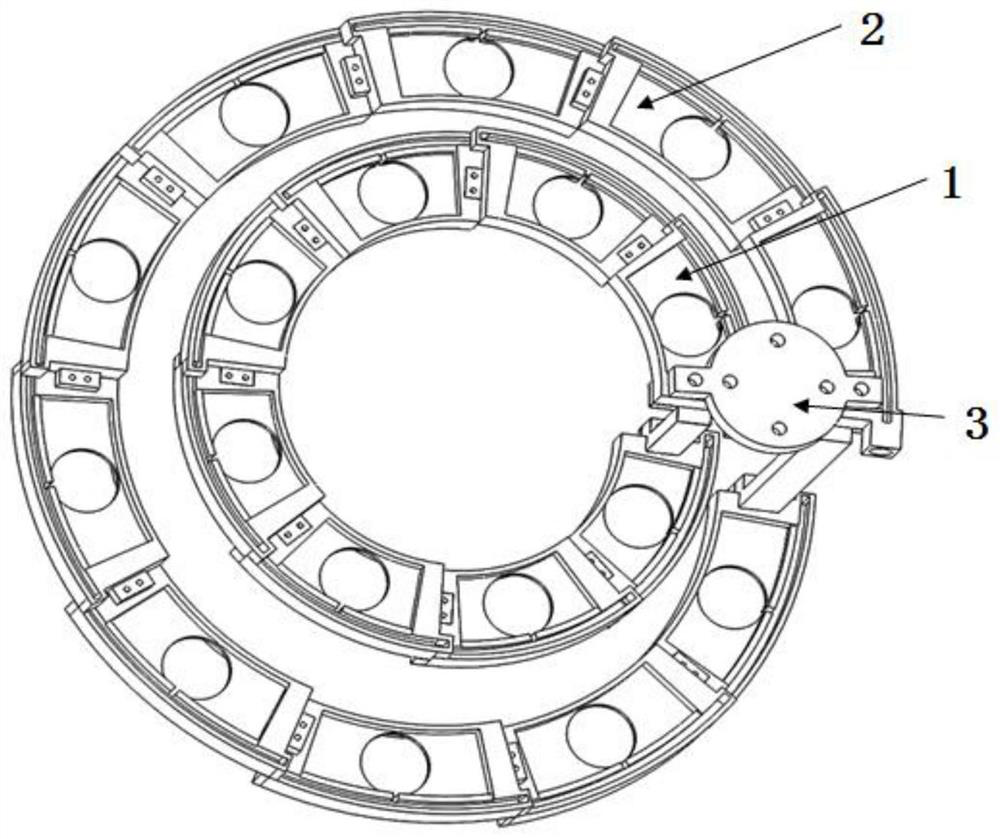
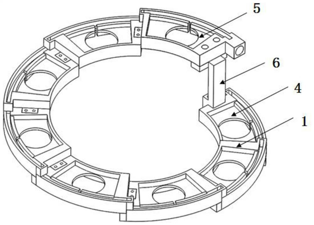
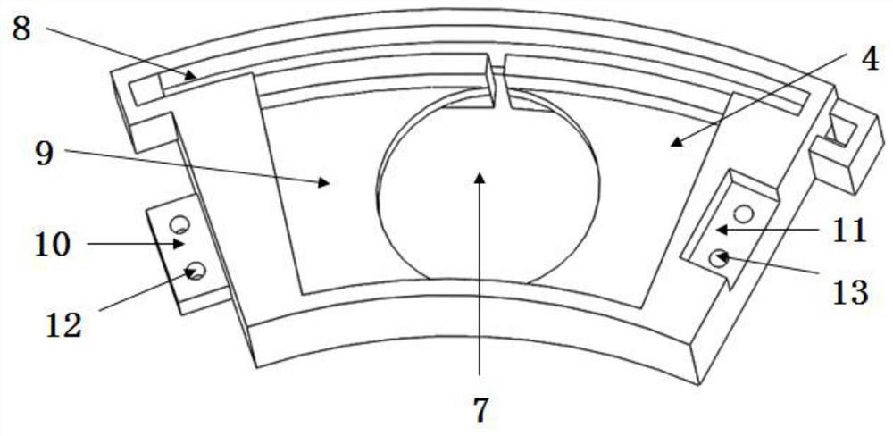
[0027] see Figure 1-7 Description of this embodiment is a multi-order acoustic orbital angular momentum emission transducer matrix, which includes a first-order acoustic orbital angular momentum emission transducer matrix 1, a second-order acoustic orbital angular momentum emission transducer matrix 2 and a basic The array positioning support 3, the primary array 1 of the first-order acoustic orbital angular momentum emission transducer and the primary array 2 of the second-order acoustic orbital angular momentum emission transducer are arranged in a spiral shape with equal spacing in space, and the two ends of the positioning support 3 of the array are respectively It is connected with the first-order acoustic orbital angular momentum emission transducer matrix 1 and the secon...


PUM


Abstract

The invention provides a multi-order acoustic orbital angular momentum transmitting transducer matrix, which belongs to the field of underwater acoustic transducers. It solves the problems that the existing acoustic orbital angular momentum emission technology is difficult to conveniently generate acoustic orbital angular momentum, and it is difficult to accurately and quickly demodulate the information contained in the acoustic orbital angular momentum. It includes a multi-order acoustic orbital angular momentum transmitting transducer matrix, which includes a first-order acoustic orbital angular momentum transmitting transducer matrix, a second-order acoustic orbital angular momentum transmitting transducer matrix and a matrix positioning bracket, The first-order acoustic orbital angular momentum transmitting transducer arrays and the second-order acoustic orbital angular momentum transmitting transducer arrays are arranged in an equal-spaced spiral, and the two ends of the array positioning brackets are respectively connected to the first-order acoustic orbital angular momentum transmitting arrays. The orbital angular momentum emitting transducer array is connected to the second-order acoustic orbital angular momentum emitting transducer array. It is mainly used for underwater acoustic communication.

Description

technical field [0001] The invention belongs to the field of underwater acoustic transducers, in particular to a multi-order acoustic orbital angular momentum transmitting transducer matrix. Background technique [0002] Acoustic waves are currently the best way for underwater long-distance information transmission. However, high-frequency sound waves still have strong attenuation in water media. Although there are methods such as differential phase shift keying and quadrature amplitude modulation to improve the information transmission of underwater acoustic communication rate, but its transmission capability is still limited by the low carrier frequency, coupled with the gradual increase in people's exploration of marine resources, and the gradual increase in the amount of modern underwater data transmission, the existing transmission rate can no longer meet the requirements of information transmission, so , it is necessary to develop a new multiplexing method to expand th...

Claims


Application Information

Patent Timeline
Patent Type & Authority Patents(China)
IPC IPC(8): H04B13/02
CPCH04B13/02
Inventor 卢苇孙浩蓝宇周天放郭荣真
Owner HARBIN ENG UNIV
Learn More