Low-temperature protection device special for camera

A low-temperature protection, camera technology, applied in the direction of camera, image communication, camera body, etc., can solve the problems of complexity, limited application, unable to develop and install normally, and achieve the effect of simple installation

Active Publication Date: 2020-07-24
NORTH CHINA INST OF AEROSPACE ENG
View PDF13 Cites 0 Cited by
  • Summary
  • Abstract
  • Description
  • Claims
  • Application Information

AI Technical Summary

Problems solved by technology

However, the existing technology generally has problems such as failure to develop normally or complicated

Method used


Image

  • Low-temperature protection device special for camera
  • Low-temperature protection device special for camera
  • Low-temperature protection device special for camera

Examples


Embodiment Construction

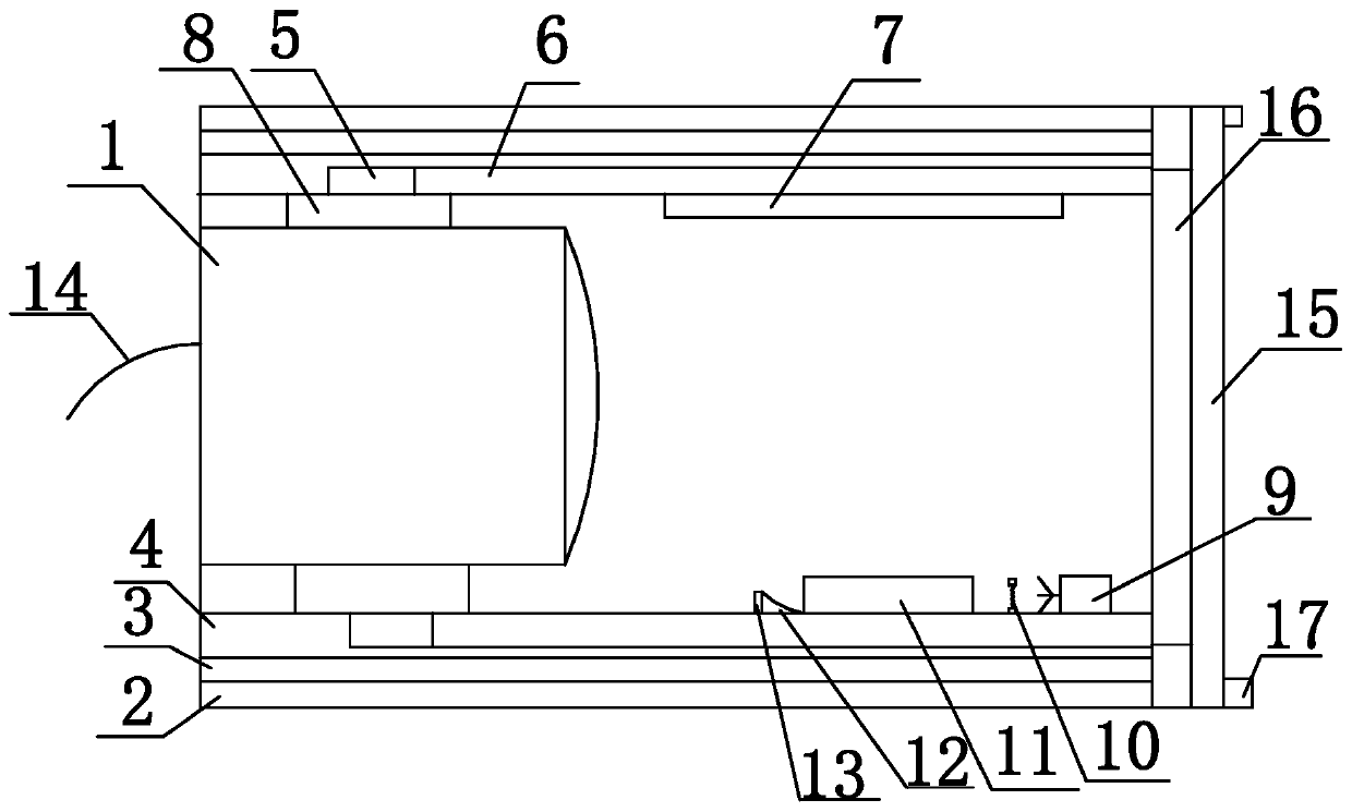
[0023] The standard parts used in the present invention can be purchased from the market, and the special-shaped parts can be customized according to the instructions and the accompanying drawings. The specific connection methods of each part adopt mature bolts, rivets, welding in the prior art , pasting and other conventional means, no longer described in detail here.

[0024] refer to Figure 1-12, a specific embodiment of the present invention includes a camera 1, one end of the clamping block 8 is crimped with the camera 1, the other end of the clamping block 8 is fixed on the inner surface of the annular cylindrical inner shell 4, and the outer surface of the annular cylindrical inner shell 4 is sleeved on the annular cylindrical phase transition The inner side of the layer 3, the outer side of the annular cylindrical phase change layer 3 is sleeved on the annular cylindrical insulation layer 2, and the side of the insulating layer 2 away from the camera 1 is fixed with a...


PUM


Abstract

The invention discloses a special low-temperature protection device for a camera. The device comprises a camera, one end of the fixture block is crimped with the camera; the other end of the clampingblock is fixed on the inner side of the annular cylindrical inner shell; the outer side surface of the annular cylindrical inner shell sleeves the inner side surface of the annular cylindrical phase change layer; the outer side surface of the annular cylindrical phase change layer sleeves the annular cylindrical heat preservation layer; an annular clamping block with a rectangular cross section isfixed to the side face, away from the camera, of the heat preservation layer. Four quadrangular clamping grooves are uniformly formed in the annular cylindrical inner shell along the inner side surface; a quadrangular frustum pyramid clamping groove is formed in the side surface of each quadrangular prism clamping groove; an annular clamping piece is fixed to the end, away from the camera, of each quadrangular frustum pyramid clamping groove, one side face of the cylindrical glass is in press connection with one annular clamping piece, the other side face of the cylindrical glass is in pressconnection with the annular clamping block, and an electric fan, an electric heating device, an air inlet guide device, an air port guide device and a fan impeller are sequentially fixed to the innerside face of the annular cylindrical inner shell. The defects in the prior art can be overcome, and normal application of the camera in a low-temperature environment is guaranteed.

Description

technical field [0001] The invention relates to a camera protection device, in particular to a special low-temperature protection device for a camera. Background technique [0002] With the improvement of people's safety awareness, cameras have gradually entered people's lives, and at the same time, higher requirements have been put forward for cameras, especially to maintain normal work in low temperature environments. However, the existing technology generally has problems such as failure to develop normally or complicated installation in a low temperature environment, which limits its application in a low temperature environment. Contents of the invention [0003] The technical problem to be solved by the present invention is to provide a special low-temperature protection device for cameras, which can solve the deficiencies of the prior art and ensure the normal application of the cameras in low-temperature environments. [0004] In order to solve the above technical ...

Claims


Application Information

Patent Timeline
IPC IPC(8): H04N5/225G03B17/56G03B17/55
CPCG03B17/55G03B17/56H04N23/50
Inventor 蔡志为杨凤龙刘宝华张梦梦刘莹穆城
Owner NORTH CHINA INST OF AEROSPACE ENG
Why Eureka
Try Eureka