
Heat dissipation device, production method of heat dissipation device and electronic equipment

A heat dissipation device and accommodating space technology, applied in the field of heat conduction, can solve problems such as flow interference, loss of heat dissipation effect, and reduction of heat transfer speed, so as to improve heat dissipation performance, facilitate heat dissipation, and ensure performance

Active Publication Date: 2020-07-24
GUANGDONG OPPO MOBILE TELECOMM CORP LTD
View PDF5 Cites 4 Cited by
  • Summary
  • Abstract
  • Description
  • Claims
  • Application Information

AI Technical Summary

Problems solved by technology

Taking the vapor chamber as an example, it uses the phase change of the working fluid to transfer heat to complete heat dissipation; however, during this process, the gaseous working fluid in the steam chamber interacts with the liquid working fluid in the capillary structure, causing mutual flow Interference, thereby reducing the heat transfer speed, affecting the heat dissipation effect, and even losing the heat dissipation effect

Method used


Image

  • Heat dissipation device, production method of heat dissipation device and electronic equipment
  • Heat dissipation device, production method of heat dissipation device and electronic equipment
  • Heat dissipation device, production method of heat dissipation device and electronic equipment

Examples


Embodiment Construction

[0024] The following are preferred embodiments of the application. It should be pointed out that for those skilled in the art, without departing from the principle of the application, some improvements and modifications can also be made, and these improvements and modifications are also considered as the present invention. The scope of protection applied for.

[0025] The following disclosure provides many different implementations or examples for implementing different structures of the present application. To simplify the disclosure of the present application, components and arrangements of specific examples are described below. Of course, they are examples only and are not intended to limit the application. Furthermore, the present application may repeat reference numerals and / or reference letters in various instances, such repetition is for simplicity and clarity and does not in itself indicate a relationship between the various embodiments and / or arrangements discussed. ...


PUM


Abstract

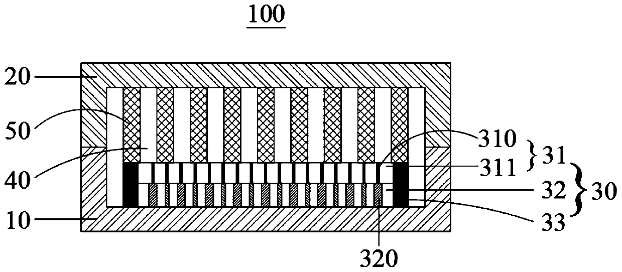
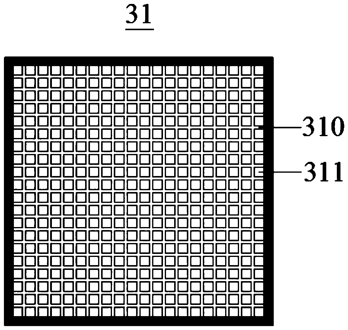
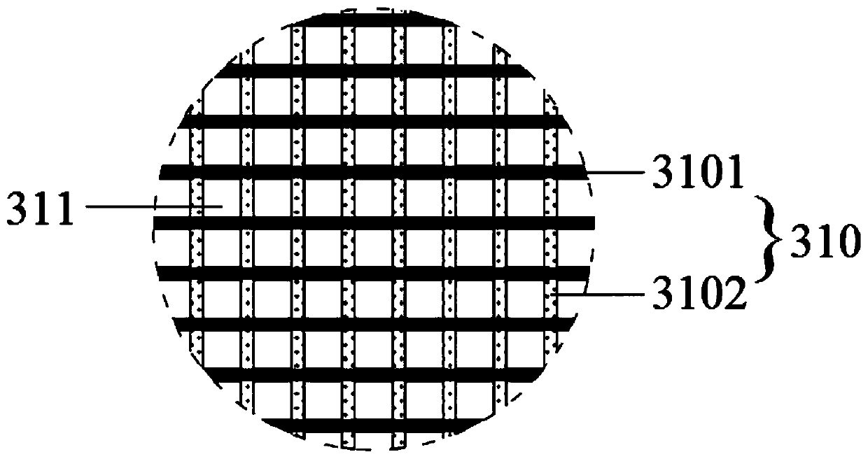
The invention provides a heat dissipation device. The device comprises a first cover plate, a second cover plate, a capillary core and a working fluid. The first cover plate and the second cover plateare covered to form a closed accommodating space; the capillary core is arranged on a surface, close to the accommodating space, of the first cover plate; the working fluid is filled in the accommodating space; the capillary core comprises a supporting layer and a capillary structure layer; and the supporting layer comprises a plurality of supporting strips and a plurality of hollow areas formedby arranging the supporting strips in a staggered mode, the capillary structure layer is arranged between the supporting layer and the first cover plate, the capillary structure layer comprises a plurality of microstructures arranged on the supporting strips at intervals, and a gap between every two adjacent microstructures is less than a transverse size of each hollow area. Each hollow area doesnot generate a capillary acting force on the working fluid so that interaction between the liquid working fluid in the capillary core and the gaseous working fluid in the accommodating space is avoided, gas-liquid separation is achieved, and heat dissipation performance of the heat dissipation device is improved.

Description

technical field [0001] The application belongs to the technical field of heat conduction, and in particular relates to a heat dissipation device, a preparation method of the heat dissipation device and electronic equipment. Background technique [0002] Electronic equipment generates heat when it is in operation, which directly leads to a sharp rise in the temperature of the electronic equipment. Therefore, it is necessary to quickly dissipate the heat with the help of a heat sink. Taking the vapor chamber as an example, it uses the phase change of the working fluid to transfer heat to complete heat dissipation; however, during this process, the gaseous working fluid in the steam chamber interacts with the liquid working fluid in the capillary structure, causing mutual flow Interference, thereby reducing the heat transfer speed, affecting the heat dissipation effect, or even losing the heat dissipation effect. Contents of the invention [0003] In view of this, the presen...

Claims


Application Information

Patent Timeline
Patent Type & Authority Applications(China)
IPC IPC(8): H05K7/20
CPCH05K7/20336
Inventor 杨鑫
Owner GUANGDONG OPPO MOBILE TELECOMM CORP LTD
Learn More