Double station vacuum die casting machine

A vacuum die-casting, double-station technology, applied in the field of precision parts forming, can solve the problems of long vacuuming time, large size of the driving device, easy aging of the sealing device, etc., and achieve the effects of reduced maintenance time, short starting distance and compact structure

Active Publication Date: 2021-03-05
YANSHAN UNIV
View PDF6 Cites 0 Cited by
  • Summary
  • Abstract
  • Description
  • Claims
  • Application Information

AI Technical Summary

Problems solved by technology

[0005] Aiming at the above problems urgently needed to be solved by the vacuum die-casting machine, the present invention provides a double-station vacuum die-casting machine, mainly by rotating the relative position of the pressure chamber, to solve the problem that the existing vacuum die-casting machine needs to apply force to keep the injection rod when opening the mold. The problem of stopping the die-casting due to vacuum in the vacuum chamber, and providing two-way linear drive based on electromagnetics, solves the problems of long vacuuming time in the vacuum chamber, large size of the driving device, and easy aging of the sealing device, and realizes double-station work. Quality and Efficiency of Amorphous Alloy Preparation

Method used


Image

  • Double station vacuum die casting machine
  • Double station vacuum die casting machine
  • Double station vacuum die casting machine

Examples


Embodiment Construction

[0051] Hereinafter, embodiments of the present invention will be described with reference to the drawings.

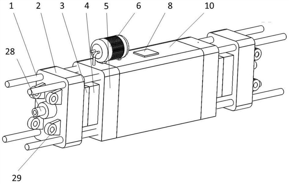
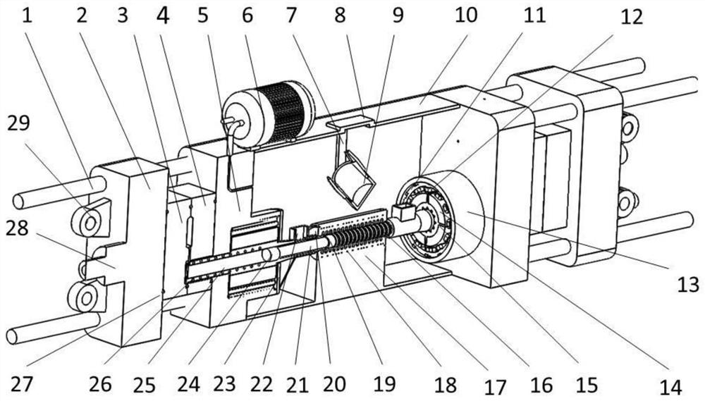
[0052] Specifically, such as Figure 1 to Figure 14 As shown, the present invention provides a double-station vacuum die-casting machine, which includes a driving device, a first die-casting unit, a second die-casting unit, a feeding component, a vacuum pump 6 and a housing 10 . The driving device is arranged inside the casing 10, and the first die-casting unit and the second die-casting unit are arranged on both sides of the driving device. The vacuum pump is located outside the casing 10 .

[0053] The drive device includes a drive unit, a first plunger assembly and a second plunger assembly. The first plunger assembly and the second plunger assembly are respectively arranged on both sides of the stator assembly. The first plunger assembly is the second plunger assembly. A die-casting unit provides die-casting power, and the second injection rod assembly provides di...


PUM


Abstract

The invention provides a double-station vacuum die-casting machine, which includes a driving device, a first die-casting unit, a second die-casting unit, a feeding part, a vacuum pump and a casing, the vacuum pump is arranged outside the casing, and the driving device is arranged on the casing Inside, the first die-casting unit and the second die-casting unit are respectively arranged on both sides of the driving device; the driving device includes the driving unit, the first injection rod assembly and the second injection rod assembly, the first injection rod assembly and the second injection rod assembly The injection rod assemblies are respectively arranged on both sides of the drive unit, the first injection rod assembly is used to provide power for the die-casting of the first die-casting unit, and the second injection rod assembly is used to provide power for the second die-casting unit; the present invention does not need to use The injection rod drives the injection punch to carry out the process of maintaining pressure on the die-casting during die-casting and the process of maintaining the vacuum in the working room when the mold is opened, and the driving device can make the mover sleeve reversely move to drive the injection rod assembly to carry out another process. The same die-casting work in one direction can greatly improve the efficiency of die-casting.

Description

technical field [0001] The invention relates to the technical field of forming precision parts, in particular to a double-station vacuum die-casting machine. Background technique [0002] Die casting is a casting process in which liquid metal in a high-temperature molten state is injected into a mold cavity at high pressure and high speed, and is cooled and solidified under pressure to obtain a casting. This casting method is characterized by precise product forming and high production efficiency. However, the conventional die-casting process has defects. Because the gas in the mold cavity cannot be effectively removed during high-speed injection, it remains inside the casting, forming pore defects, resulting in poor mechanical properties of the casting. In order to solve this problem, people adopt the method of vacuuming, that is, the gas in the cavity is drawn out during die-casting to form a certain vacuum or negative pressure state, thereby reducing the pore defects ins...

Claims


Application Information

Patent Timeline
Patent Type & Authority Patents(China)
IPC IPC(8): B22D17/14B22D17/20B22D17/32B22D17/22B22D17/04
CPCB22D17/14B22D17/2015B22D17/32B22D17/22B22D17/04B22D17/2023
Inventor 金昕于学千詹望金渊哲
Owner YANSHAN UNIV
Why Eureka
Try Eureka