Belt conveyor capable of automatically regulating belt tension

A belt tension and automatic adjustment technology, applied in the field of conveyor belts, can solve the problems that the adjustment structure cannot be adjusted in real time, and the conveyor belt force is unstable.

Active Publication Date: 2020-07-28
山东海纳智能装备科技股份有限公司
View PDF6 Cites 3 Cited by
  • Summary
  • Abstract
  • Description
  • Claims
  • Application Information

AI Technical Summary

Problems solved by technology

[0006] Aiming at the deficiencies of the prior art, the present invention provides a belt conveyor that can automatically adjust the tension of the belt, which has the advantages of automatically changing the position of the adjustment structure according to the working conditions, self-tensioning of the conveyor belt, and stable force on the conveyor belt. , to solve the problem that the adjustment structure cannot be adjusted in real time during the working process, and when the spring is used for adjustment, the spring force often gradually decreases as the conveyor belt relaxes, and the force on the conveyor belt is unstable.

Method used


Image

  • Belt conveyor capable of automatically regulating belt tension
  • Belt conveyor capable of automatically regulating belt tension
  • Belt conveyor capable of automatically regulating belt tension

Examples


Embodiment Construction

[0023] The following will clearly and completely describe the technical solutions in the embodiments of the present invention with reference to the accompanying drawings in the embodiments of the present invention. Obviously, the described embodiments are only some, not all, embodiments of the present invention. Based on the embodiments of the present invention, all other embodiments obtained by persons of ordinary skill in the art without making creative efforts belong to the protection scope of the present invention.

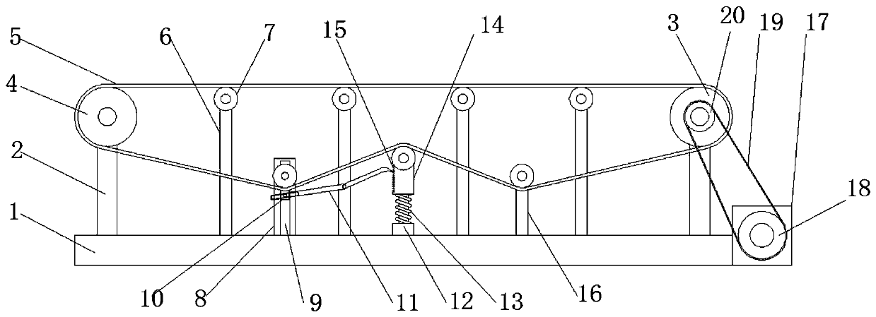
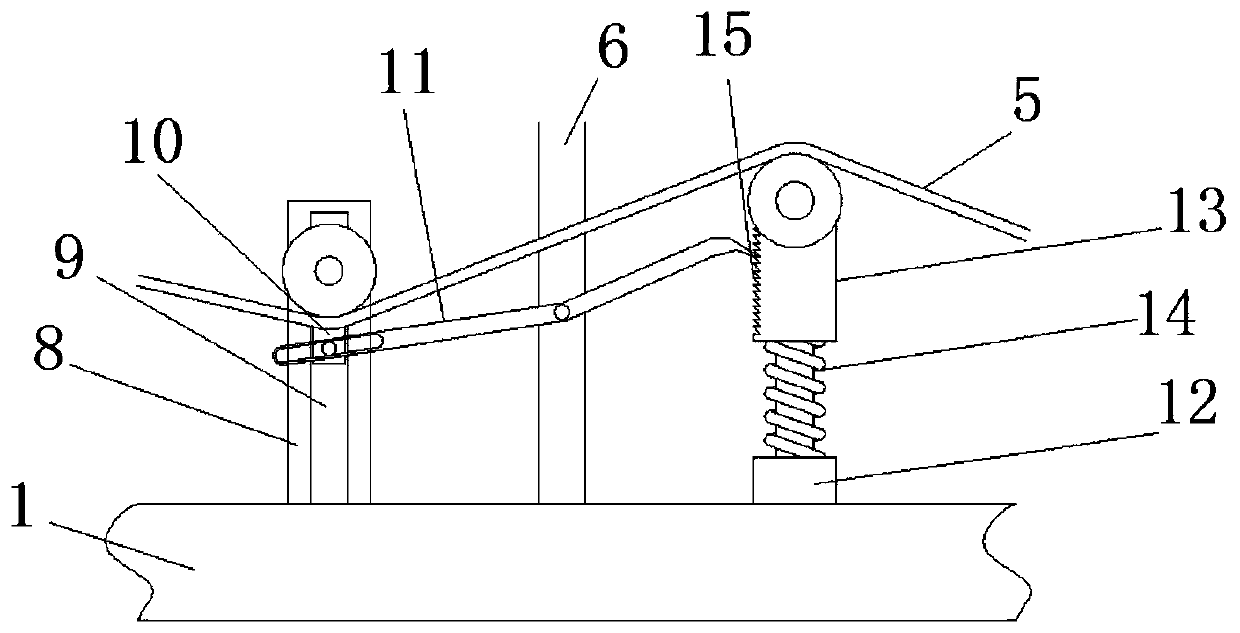
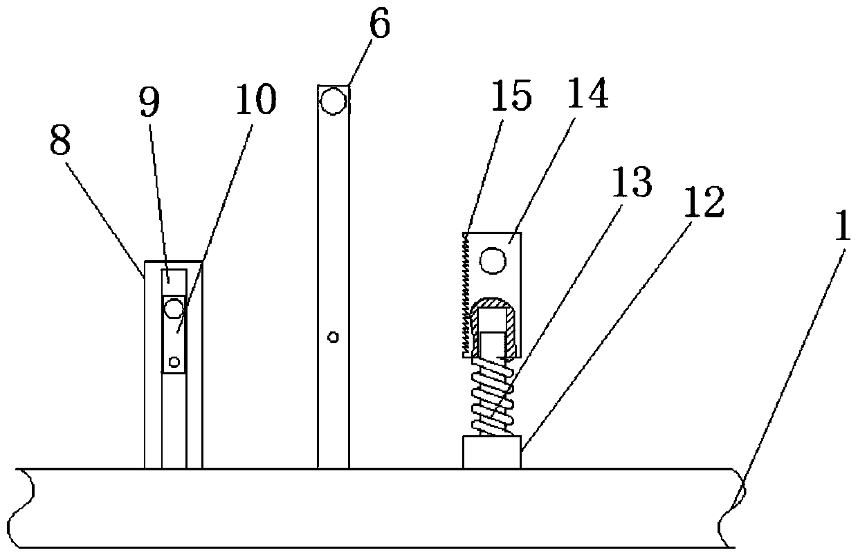
[0024] see Figure 1-3 , a belt conveyor that can automatically adjust the tension of the belt, including a base 1, the two sides of the base 1 are respectively fixedly connected with a main support 2, and the tops of the two main supports 2 are rotatably connected with a transmission roller 3 and a driven roller 4, and the transmission roller The front of 3 is fixedly connected with a driven wheel 20, the top of the base 1 is fixedly connected with a high sup...


PUM


Abstract

The invention relates to the technical field of conveying belts, and further discloses a belt conveyor capable of automatically regulating belt tension. The belt conveyor comprises a base, wherein high supporting rods and a low supporting rod are fixedly connected to the top of the base and are further located on two primary brackets; an auxiliary bracket is fixedly connected to the top of the base and is further located between two high supporting rods on the left side; the front face of the auxiliary bracket is provided with a sliding chute; the interior of the sliding chute is connected with a sliding block in a sliding manner; the bottom of the sliding block is rotationally connected with a clamping hook; a convex column is fixedly connected to the top of the base and is further located between the auxiliary bracket and the low supporting rod; the top of the convex column is connected with a sleeving column in an insertion manner; the left side of the sleeving column is provided with a tooth space; and the top of the convex column is connected with a spring in a sleeving manner. By the sliding between the sliding chute and the sliding block, the sliding block is downwards movedwhen a conveying belt is loose; the clamping hook is separated from the tooth space; the sleeving column is enabled to rise by the spring; the conveying belt is tightened; the sliding block is upwards moved; the clamping hook is completely locked with the tooth space; and the sleeving column is fixed.

Description

technical field [0001] The invention relates to the technical field of conveyor belts, in particular to a belt conveyor that can automatically adjust the tension of the belt. Background technique [0002] Belt conveyor is a continuous conveying machine that uses a flexible conveyor belt as a material bearing and traction member. It is mainly used for continuous or intermittent motion to convey various items of different weights. It can perform certain process operations on assembly lines and logistics transportation operations. . Generally, it is transported in horizontal and inclined directions. [0003] However, the structure of the belt conveyors on the market is complex. Currently, there are three methods for adjusting the tension of the conveyor belt: the vertical hammer type, the fixed type and the hydraulic type. However, most of the adjustment structures cannot be adjusted in real time during the working process, and When the spring is used for adjustment, the elas...

Claims


Application Information

Patent Timeline
Patent Type & Authority Applications(China)
IPC IPC(8): B65G23/44B65G15/32B65G15/60B65G23/04B65G23/22
CPCB65G15/32B65G15/60B65G23/04B65G23/22B65G23/44
Inventor 徐卫星
Owner 山东海纳智能装备科技股份有限公司
Why Eureka
Try Eureka