Automated, wireless, cargo restraint tension control and monitoring system

a technology of tension control and monitoring system, which is applied in the direction of force/torque/work measurement apparatus, instruments, transportation items, etc., can solve the problems of increasing unable to alert drivers that the load has shifted, and the restraint has come loose or even lost, so as to increase the probability of loosening event.

Active Publication Date: 2021-12-28
SMART SECUREMENT SYST LLC
View PDF23 Cites 3 Cited by
  • Summary
  • Abstract
  • Description
  • Claims
  • Application Information

AI Technical Summary

Benefits of technology

[0010]In an embodiment, a method of restraining cargo includes: coupling the ends of a cargo restraint system, as described herein, to a cargo carrier and a vehicle. A motor of the cargo restrain system is operated to increase the tension on the securing member to secure the cargo.

Problems solved by technology

Shifting and loose cargo on any vehicle threatens the vehicle, those piloting the vehicle and those near the vehicle who may be impacted by the cargo if it is accidentally released.
Such stops are dangerous and time consuming.
Passive tie down systems are incapable of alerting the drivers that the load has shifted, the restraint has come loose or even that the cargo has been lost.
In addition, many pieces of cargo, such as large air conditioning units, require a limited holding force to ensure that the cargo is not bent, distorted or ruined by overtightening, which increases the probability of a loosening event.
In addition, many of workers are reaching the end of their careers such that the effort to secure the cargo often results in strains and injury.
The restraint devices such as chains and binders are heavy, require crawling around the vehicle, dragging such devices around the load, and lacing chains in and around the lashing points, activities which become more difficult as one ages.
In addition, regardless of age, securing cargo is a time-consuming activity and anything that reduces the time involved will produce significant cost savings.
In addition, the “dumb” security devices have no means of informing the user if and when a securing device has or will loosen to the point of losing the cargo.

Method used


Image

  • Automated, wireless, cargo restraint tension control and monitoring system
  • Automated, wireless, cargo restraint tension control and monitoring system
  • Automated, wireless, cargo restraint tension control and monitoring system

Examples


Embodiment Construction

[0028]It is to be understood the present invention is not limited to particular devices or methods, which may, of course, vary. It is also to be understood that the terminology used herein is for the purpose of describing particular embodiments only, and is not intended to be limiting. As used in this specification and the appended claims, the singular forms “a”, “an”, and “the” include singular and plural referents unless the content clearly dictates otherwise. Furthermore, the word “may” is used throughout this application in a permissive sense (i.e., having the potential to, being able to), not in a mandatory sense (i.e., must). The term “include,” and derivations thereof, mean “including, but not limited to.” The term “coupled” means directly or indirectly connected.

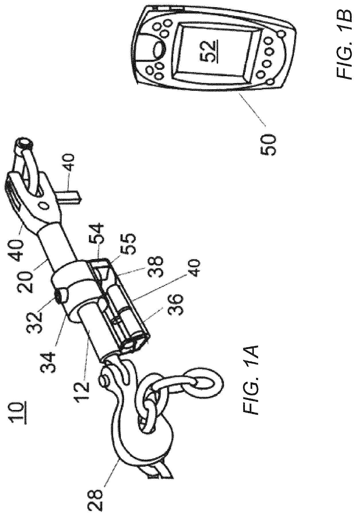
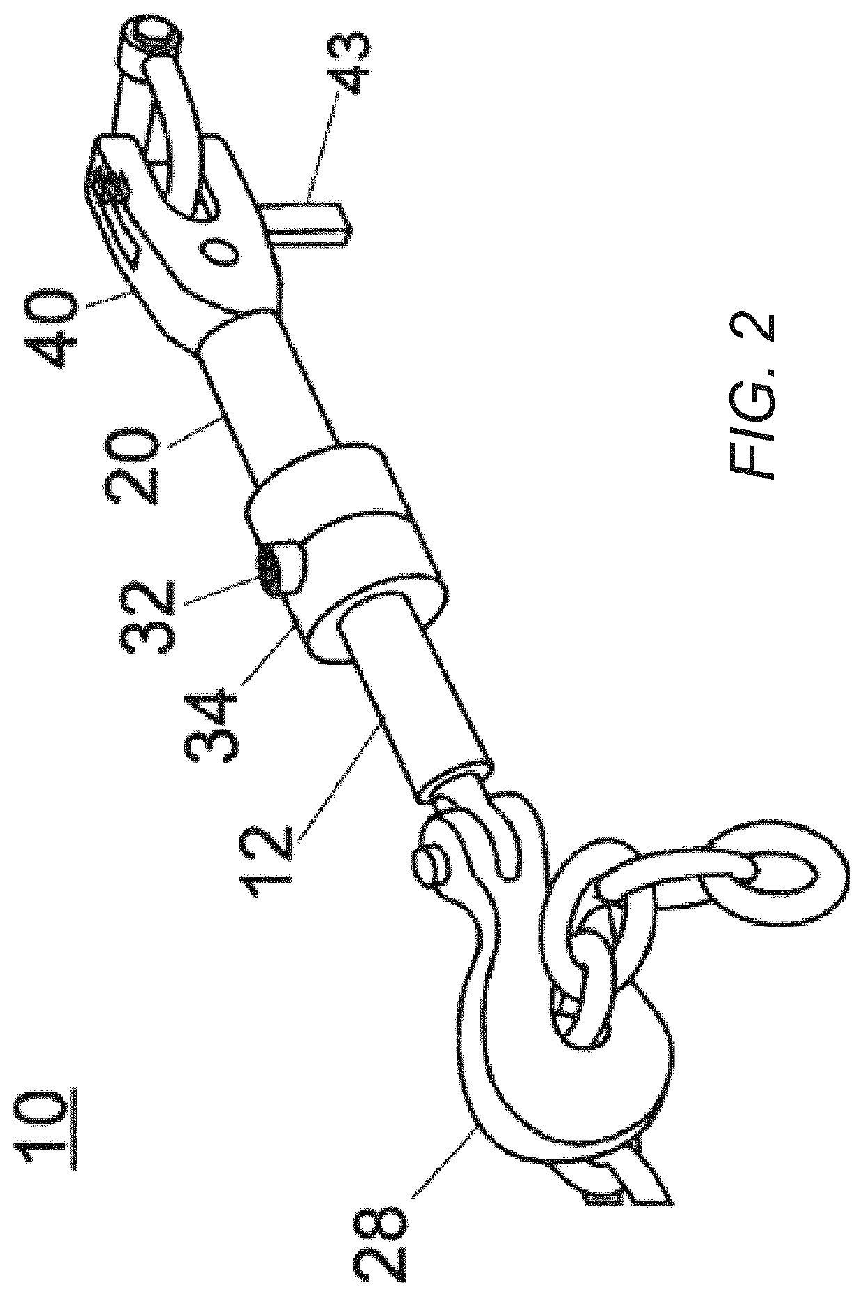
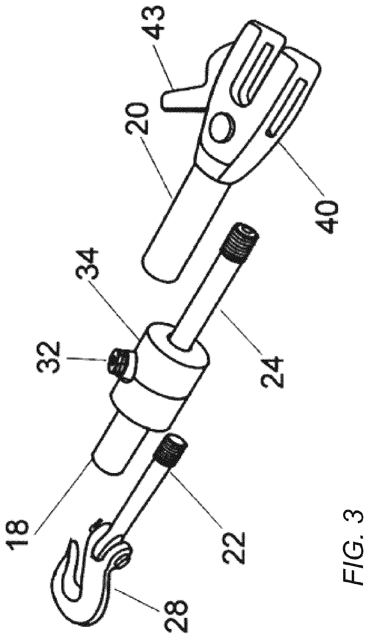
[0029]Referring to FIGS. 1-8, there is shown a first embodiment of a cargo restraint system 10. As shown in FIG. 1, system 10 includes a powered restraint system 12 that is used to create a self-tightening and self-r...


PUM

PropertyMeasurementUnit
shear strengthaaaaaaaaaa
aspect ratiosaaaaaaaaaa

Abstract

A cargo restraint system a locking ring coupled to an extension tube, wherein the locking ring comprises an annular body and one or more tabs extending from the annular body. The cargo restrain system also includes a locking tube coupled to the main body. The locking tube comprises one or more grooves complementary to the shape and size of the tabs on the locking ring. The grooves of the locking tube inhibit rotational movement of the locking ring.

Description

PRIORITY CLAIM[0001]This application claims priority to U.S. Provisional Application Ser. No. 62 / 797,938 entitled “AUTOMATED, WIRELESS, CARGO RESTRAINT TENSION CONTROL AND MONITORING SYSTEM” filed Jan. 28, 2019; which is incorporated herein by reference in its entirety.BACKGROUND OF THE INVENTIONField of the Invention[0002]The invention generally relates to cargo restraint systems. More specifically, the invention relates to cargo restraint systems that include a smart controller that monitors the status of the cargo restraint system.Description of the Relevant Art[0003]The restraint of cargo is one of the critical technologies for the movement of all logistics. Shifting and loose cargo on any vehicle threatens the vehicle, those piloting the vehicle and those near the vehicle who may be impacted by the cargo if it is accidentally released. Almost daily there are news stories about drivers and passengers of vehicles that are injured, or even killed, by cargo that has been accidental...

Claims


Application Information

Patent Timeline
Patent Type & Authority Patents(United States)
IPC IPC(8): B60W50/14B60P7/08G01L1/00
CPCB60P7/0861B60W50/14B60P7/0807B60W2050/143B60W2050/146G01L1/00G01L5/101B60P7/083
Inventor RAINONE, MICHAEL D.SACKETT, SAMUEL A.VANCE, ADAM C.BAMMEL, SCOTTY J.CRIPPEN, THOMAS E.GRISHAM, BROOK
Owner SMART SECUREMENT SYST LLC
Why Eureka
Try Eureka