Tension control mechanism of annular coil winding machine

A tension control mechanism, technology of annular coil

Inactive Publication Date: 2012-05-23
THE NORTHWEST MACHINE
View PDF0 Cites 4 Cited by
  • Summary
  • Abstract
  • Description
  • Claims
  • Application Information

AI Technical Summary

Problems solved by technology

[0004] The technical problem to be solved by the present invention is to provide a tension control mechanism for a toroidal coil winding machine in view of the deficiencies in the prior art. The mechanism is simple and the design is reasonable. The problem of enameled wire becoming loose, and the winding tension of the toroidal coil winding machine can be automatically adjusted to meet the requirements of stable tension during the coil winding process

Method used


Image

  • Tension control mechanism of annular coil winding machine
  • Tension control mechanism of annular coil winding machine

Examples


Embodiment Construction

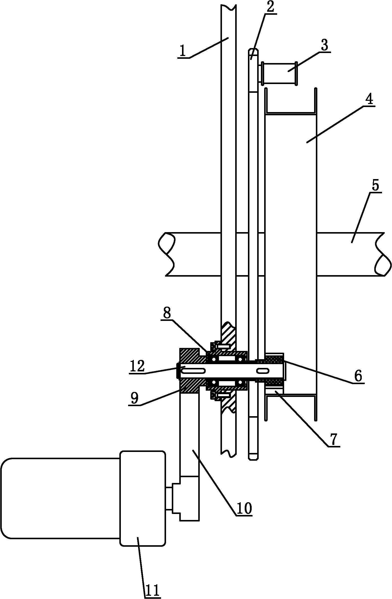
[0018] Such as figure 1 The tension control mechanism of a toroidal coil winding machine shown includes a machine head wall plate 1, an iron core 5 vertically installed on the machine head wall plate 1, a shuttle 2 arranged on the right side of the machine head wall plate 1, a fixed installation The extractor 3 on the right side of the upper part of the shuttle 2 and the wire storage ring 4 arranged on the right side of the shuttle 2, the iron core 5 is vertically installed on the wire storage ring 4, and the inside of the wire storage ring 4 is provided with an inner ring gear 7. The inner ring gear 7 is located at the lower part of the wire storage ring 4, and the lower part of the wire storage ring 4 is provided with a transmission shaft 12 passing through the machine head wallboard 1, the shuttle 2 and the wire storage ring 4, and the right end of the transmission shaft 12 is The gear 6 meshing with the ring gear 7 is installed, the left end of the transmission shaft 12 is...


PUM


Abstract

The invention discloses a tension control mechanism of an annular coil winding machine, which comprises a head wallboard, an iron core which is vertically installed on the head wallboard, a shuttle which is arranged on the right of the head wallboard, a pickup device which is fixedly installed on the right side of the upper part of the shuttle, and a coil storage ring which is arranged on the right of the shuttle, wherein the iron core is vertically installed on the coil storage ring, an inner gear ring is arranged in the coil storage ring and is arranged at the lower part of the coil storage ring, a transmission shaft which penetrates through the head wallboard, the shuttle and the coil storage ring is arranged at the lower part of the coil storage ring, a gear which is engaged with the inner gear ring in a driving way is installed at the right end of the transmission shaft, a belt wheel is installed at the left end of the transmission shaft, a torque motor is arranged on the left side below the belt wheel, and a synchronous belt which is used for driving the belt wheel to drive is arranged between the torque motor and the belt wheel. The tension control mechanism of the annular coil winding machine has the advantages that the structure is simple, the design is reasonable, the problem that enameled wires get loose during winding in the prior art can be effectively solved, and the demand for stable tension during coil winding is met.

Description

technical field [0001] The invention relates to a tension control mechanism, in particular to a tension control mechanism of a ring coil winding machine used for current transformer products. Background technique [0002] The toroidal coil winding machine is a kind of equipment widely used in the power electronics industry. It is mainly used to wind the enameled wire on the ring frame, and wrap the iron core ring frame according to the coil process requirements. The equipment consists of two parts: the host machine and the wire pay-off mechanism. Its working principle is to drive the wire storage ring to rotate through the reverse rotation of the shuttle to wind the enameled wire on the pay-off frame into the wire storage ring, and then pull out the wire storage ring by the forward rotation of the shuttle. The enameled wire in it is wound on the iron core. However, when the annular iron core is clamped, it is generally difficult to ensure that the cross section of the annul...

Claims


Application Information

Patent Timeline
Patent Type & Authority Applications(China)
IPC IPC(8): H01F41/08B65H59/38
Inventor 吕志让杨少林马武平李东涛杨晓红
Owner THE NORTHWEST MACHINE
Why Eureka
Try Eureka