A capping system for filling glass jars

A glass jar and filling technology, which is applied in the direction of tightly closing the container with the lid, application, packaging, etc., can solve the problems of broken bottles and the inability of the bottles to rotate, and achieve the effect of reducing the cracking of cans.

Active Publication Date: 2021-11-16
新沂市铭达玻璃有限公司
View PDF9 Cites 0 Cited by
  • Summary
  • Abstract
  • Description
  • Claims
  • Application Information

AI Technical Summary

Problems solved by technology

[0002] Glass jar filling machine For some liquid processing industries such as beverages and wine, the glass jar filling machine adopts equal volume filling, the filling capacity range is large, and it is suitable for many bottle types. The glass jar has a wide range of characteristics, and the measuring cup type is used Quantitative filling valve ensures high filling accuracy. The liquid flows down along the bottle wall during filling, which effectively controls the foam caused by liquid impact during filling and prevents liquid from overflowing. However, during the bottle feeding process, the bottle is located in front of the auger. The arrangement of the position is very compact, so that the bottle cannot be rotated, so that the bottle is prone to breakage when the bottle is fed to the auger.

Method used


Image

  • A capping system for filling glass jars
  • A capping system for filling glass jars
  • A capping system for filling glass jars

Examples


Embodiment 1

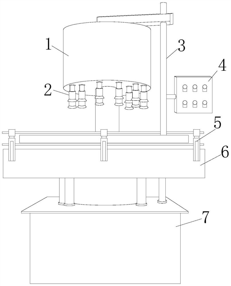
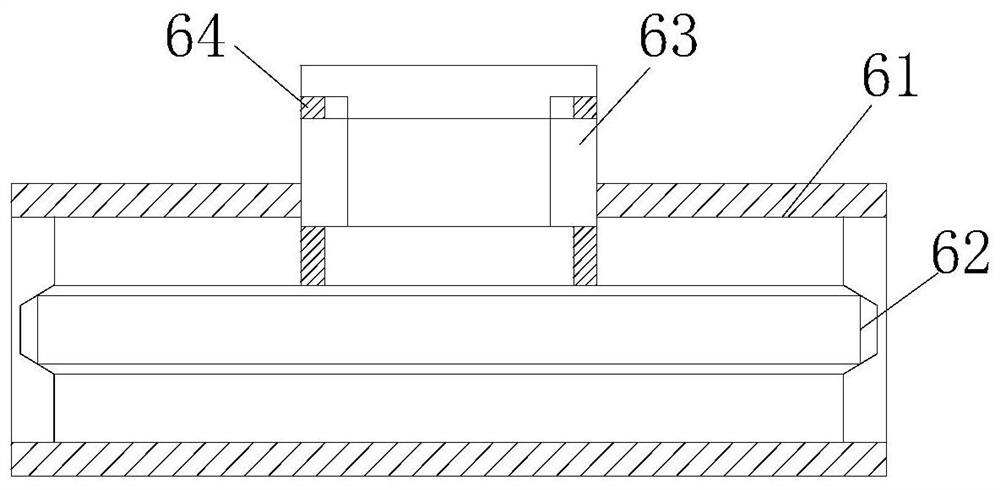
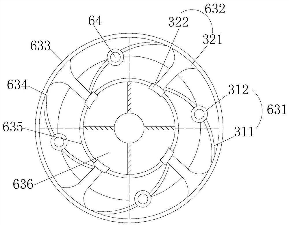
[0025] Such as Figure 1-Figure 4 As shown, the present invention provides a capping system for filling glass jars, the structure of which includes a capping box 1, a lower lid opening 2, a pole 3, a control electric box 4, an installation shaft 5, a transmission slot 6, and a main machine Box 7, the bottom of the lidded box 1 is equipped with a lower cover opening 2, the top of the covered box 1 is arranged on the main box 7 through a pole 3, the signal end of the main box 7 is connected to the control electric box 4 Electrically connected, the transfer slot 6 is driven by the main chassis 7, the transfer slot 6 is provided with an installation shaft 5, and the transfer slot 6 is provided with a grid base 61, an auger engagement shaft 62, a bottle holder 63, Engaging rotating shaft 64, described grid base 61 is provided with auger engaging shaft 62, and described auger engaging shaft 62 engages with engaging rotating shaft 64, and described engaging rotating shaft 64 cooperat...

Embodiment 2

[0027] Such as Figure 5 As shown, the side adsorption chamber 322 is provided with a raised soft side 22a, a pressure port 22b, a pressure generator 22c, and a protective shell 22d, and the two sides of the pressure port 22b are provided with a raised soft side 22a, and the pressure port 22b is connected to the pressure generator 22c, and the pressure generator 22c is installed inside the protective shell 22d, and a raised soft edge is provided in the edge adsorption cavity to cooperate with the pressure port. When the pressure port generates pressure, the adsorbed glass jar contacts the depression. Make the can body touch the raised soft edge to reduce the cracking of the can caused by hard collision.

[0028] The working principle of the capping system in the above-mentioned technical scheme is described as follows:

[0029] When the present invention sends bottle, glass jar is to the inside of bottle holder 63, just when not entering auger, as Figure 4 As shown, the swi...


PUM


Abstract

The invention discloses a capping system for filling glass jars. Its structure includes a capping box, a lower lid opening, a support rod, a control electric box, an installation shaft, a transmission groove, and a main box. The bottom of the capping box is installed with a The lower cover opening, the top of the covered box is set on the main box through the support rod, the signal end of the main box is electrically connected with the control electric box, the transmission slot is driven by the main box, and the transmission slot is equipped with a mounting shaft, and the transmission slot is provided with Mesh base, auger meshing shaft, bottle holder, meshing shaft, the grid base is provided with an auger meshing shaft, the auger meshing shaft meshes with the meshing shaft, the meshing shaft cooperates with the bottle holder, and the push piece is in the bottle feeding Finally, the meshing shaft of the auger meshes with the auger, and the meshing shaft drives the balance wheel to drive the arc-shaped swing bar to open, and the side adsorption chamber separates the tank body, and the opening of the side adsorption chamber expands the swing area of ​​the glass jar, and the fan cavity is extruded and matched to form A negative pressure port is adsorbed and fixed to the bottom of the glass tank, and fixed from the tank body to the bottom, making it more stable during rotation.

Description

technical field [0001] The invention relates to the field of glass jar capping machinery, in particular to a capping system for filling glass jars. Background technique [0002] Glass jar filling machine For some liquid processing industries such as beverages and wine, the glass jar filling machine adopts equal-volume filling, with a large range of filling capacity and many applicable bottle types. Glass jars have a wide range of characteristics. Quantitative filling valve ensures high filling accuracy. The liquid flows down along the bottle wall during filling, which effectively controls the foam caused by liquid impact during filling and prevents liquid from overflowing. However, during the bottle feeding process, the bottle is located in front of the auger. The arrangement of the position is very compact, so that the bottle cannot be rotated, and the bottle is prone to breakage when the bottle is fed to the auger. Contents of the invention [0003] In view of the above...

Claims


Application Information

Patent Timeline
Patent Type & Authority Patents(China)
IPC IPC(8): B67B3/00B65G29/00
CPCB65G29/00B67B3/00
Inventor 刘振勇
Owner 新沂市铭达玻璃有限公司
Why Eureka
Try Eureka