Arrangement method of linear adjustment and vibration reduction structure for cable rail high overhead rail structure

A technology of vibration-reducing structure and layout method, which is applied in the direction of tracks, roads, buildings, etc., can solve the problems of aggravating upper stability and structural torsional vibration, and achieve the effects of reducing lateral torsional vibration, improving stability, and improving driving stability

Active Publication Date: 2020-07-28
TONGJI UNIV
View PDF8 Cites 2 Cited by
  • Summary
  • Abstract
  • Description
  • Claims
  • Application Information

AI Technical Summary

Problems solved by technology

Due to the above-mentioned reasons, the structure may produce obvious torsional vibration. Under a certain excitation, this torsional vibration will intensify and lead to the stability of the upper part. Even if the suspended vehicle load is used, the torsional vibration of the structure will still be caused.

Method used


Image

  • Arrangement method of linear adjustment and vibration reduction structure for cable rail high overhead rail structure
  • Arrangement method of linear adjustment and vibration reduction structure for cable rail high overhead rail structure
  • Arrangement method of linear adjustment and vibration reduction structure for cable rail high overhead rail structure

Examples


Embodiment Construction

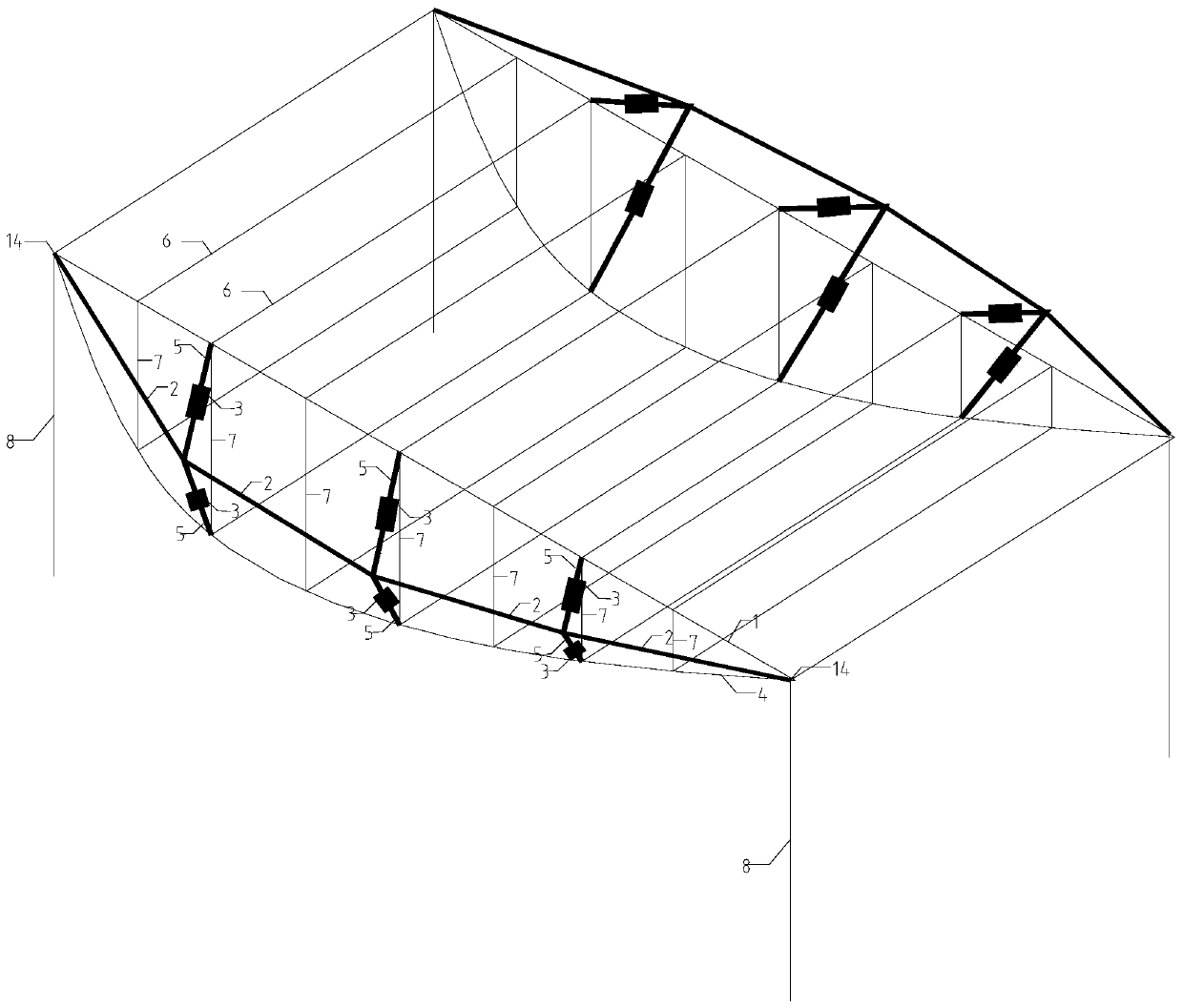
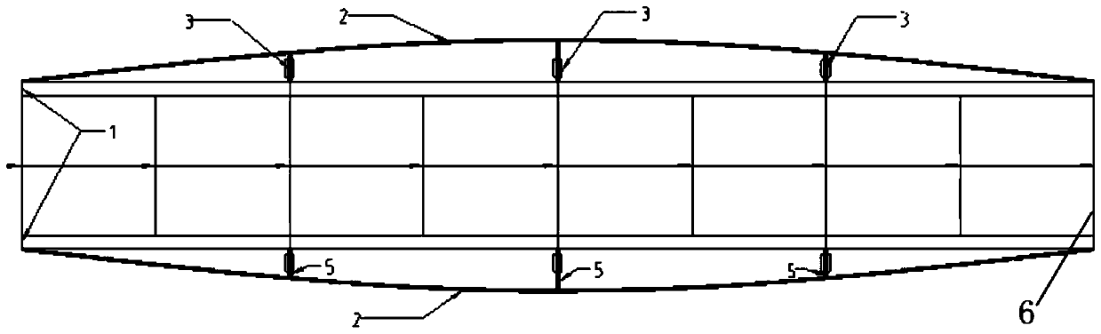
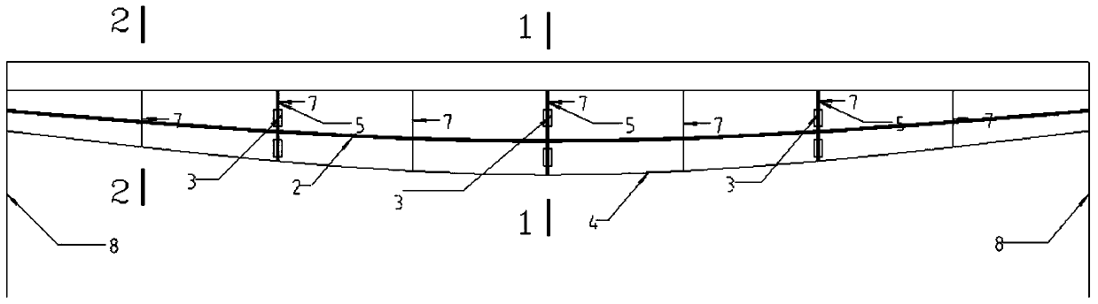
[0030] like Figure 1-5 Shown in , 8: a kind of arrangement method that is used for the linear adjustment of cable rail elevated aerial rail structure and damping structure, existing empty rail structure comprises two parallel tracks 1 and the main cable that is respectively positioned at the bottom of track 1 4. The two parallel rails 1 are connected by transverse connecting rods 6, the rails 1 and the main cables 4 below them are connected by vertical struts 7, and supporting piers 8 are provided around the bottom of the empty rail structure; It is characterized in that it comprises the following steps:

[0031] Step 1: Install the tie rod cable 2;

[0032] In view of the deflection caused by the asymmetry of the main cable 4 force on both sides of the existing empty track structure, a bundle of tie rod cables 2 is installed on both sides of the empty track structure, and the tie rod cables 2 are respectively located on the structural plane of the track 1 and the main cable...


PUM


Abstract

The invention relates to an arrangement method of a linear adjustment and vibration reduction structure for a cable rail high overhead rail structure. The arrangement method comprises the steps that 1, a pull rod cable is installed; a pull rod cable is mounted at each of the two sides of the overhead rail structure and located in the outer side of the structural plane of the rail and a main cable,and linear adjustment is achieved through the pull rod cables; 2, two supporting rods and a shock absorber are installed; a plurality of supporting rods with shock absorbers are arranged on a bundleof pull rod cables, and the pull rod cables, the two supporting rods and the shock absorbers form a shock absorption device in a vertical dimension and a transverse dimension, so that transverse torsional vibration is reduced, and the running stability of a vehicle is improved; and 3, lateral force is increased, and transverse rigidity is increased; force generated by the pull rod cable is transmitted through the upper supporting rod and the lower supporting rod, and horizontal and vertical deformation overcoming force, namely the gravity rigidity effect, is added to the upper structure of theoverhead rail. The two supporting rods are used for improving the horizontal deformation resistance of the overhead rail structure in the horizontal direction, and the two supporting rods are used for improving the overall vertical deformation resistance of the overhad rail structure in the vertical direction.

Description

technical field [0001] The invention relates to the field of aerial rails, in particular to a method for line adjustment and vibration-damping structure arrangement of a cable rail elevated aerial rail structure. Background technique [0002] The aerial track patent is an innovative transportation system. Due to the light structure, when the moving load acts on it, it will cause lateral torsional vibration of the structure, which will affect the driving comfort and cause rollover and rollover in severe cases. Experimental research shows that this phenomenon is more obvious at low and medium speeds. The reason is that under the action of moving load, the lateral deformation of the structure caused by the structure itself and the load is amplified under the dynamic characteristics, but the lateral direction of the structural system lacks the source of stiffness to resist deformation. [0003] After the invention patents 201010254005.9 and 201210009152.9 of cable rail elevated...

Claims


Application Information

Patent Timeline
IPC IPC(8): E01B25/16E01B25/18
CPCE01B25/16E01B25/18
Inventor 李方元
Owner TONGJI UNIV
Why Eureka
Try Eureka