Column prefabricated member and manufacturing method and installation construction method thereof

A technology of prefabricated parts and column formwork, applied in the direction of columns, piers, pillars, etc., can solve the problems of difficult quality control, cumbersome construction process, and the structural column cannot fully exert the overall cooperative bearing capacity, so as to improve the assembly construction efficiency and reduce the The effect of workload

Pending Publication Date: 2020-07-28
GUANGDONG UNIV OF PETROCHEMICAL TECH
View PDF0 Cites 2 Cited by
  • Summary
  • Abstract
  • Description
  • Claims
  • Application Information

AI Technical Summary

Problems solved by technology

[0004] 1. The installation and construction process of prefabricated cavity columns is complex
The installation method is "first connect the column with the lower column and temporarily fix it, then connect the longitudinal steel bars in the steel skeleton of the column with the lower column, install the tie steel bars in the connecting section, and weld the steel plate to form a steel pipe. Close the connection section, weld the steel pipe and the longitudinal steel bar in the connection section, and finally remove the temporary fixing device after pouring concrete in the cavity in the connection section", the construction process of this cavity column connection method is very cumbersome, and the quality is not easy to control
[0005] 2. After the prefabricated cavity column is poured with concrete to form the structural column, the longitudinal steel bars are likely to buckle first when the force is applied, resulting in the inability of the structural column to fully exert the overall cooperative bearing capacity

Method used


Image

  • Column prefabricated member and manufacturing method and installation construction method thereof
  • Column prefabricated member and manufacturing method and installation construction method thereof
  • Column prefabricated member and manufacturing method and installation construction method thereof

Examples


Embodiment 1

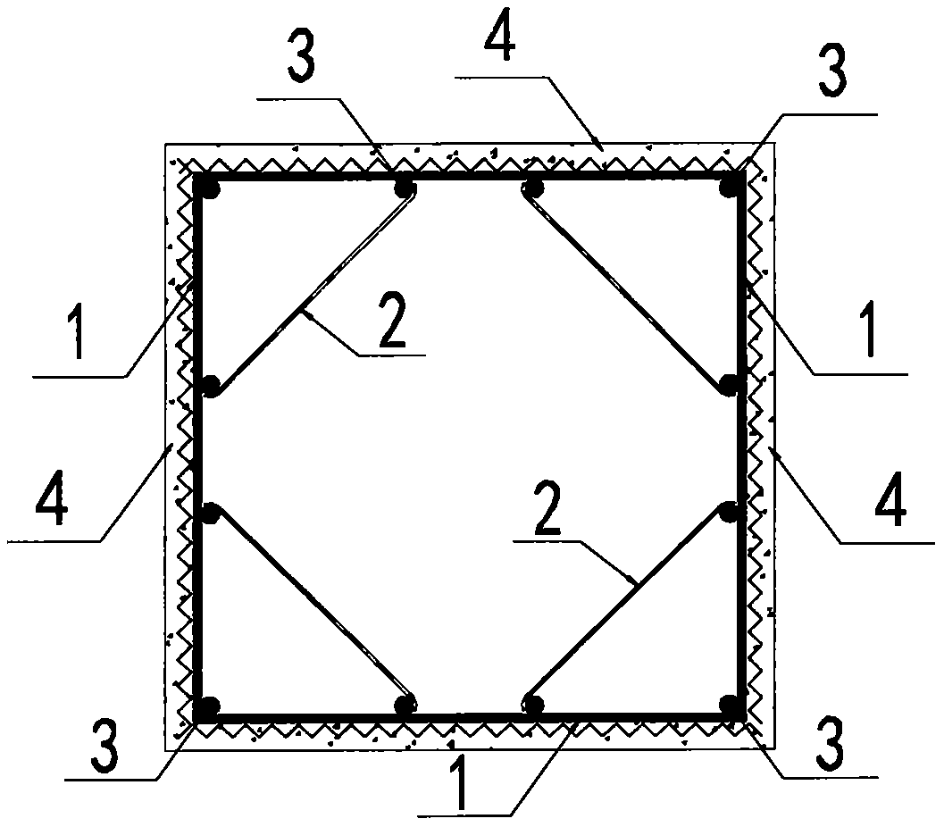
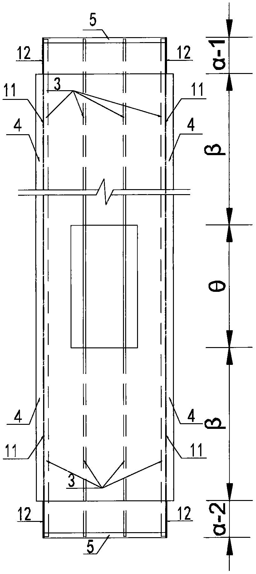
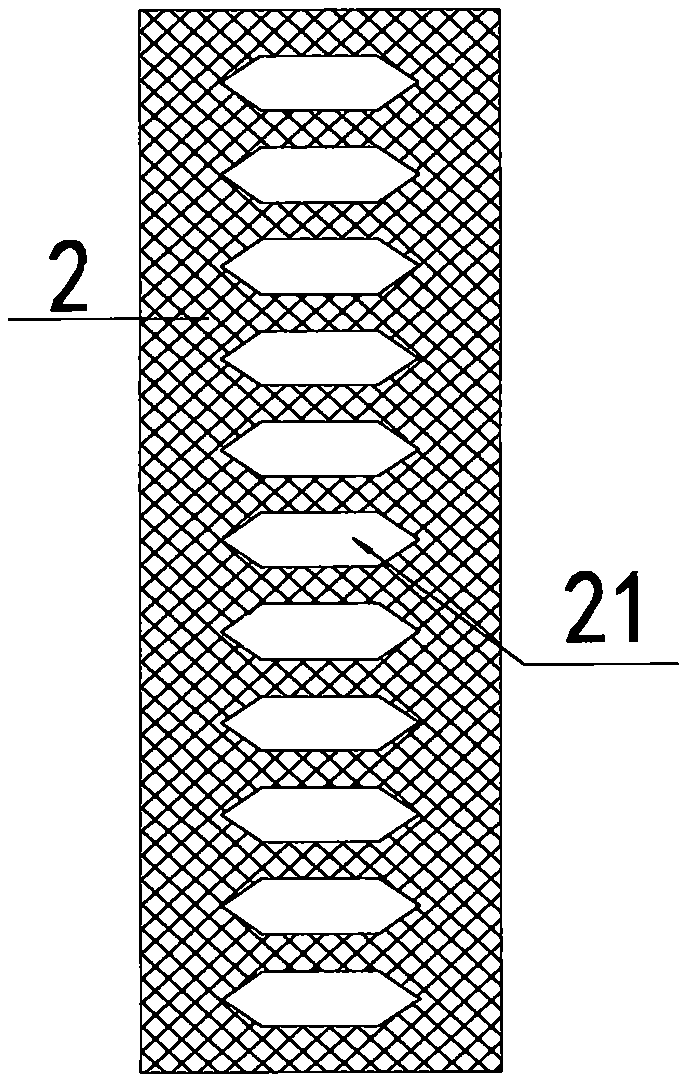
[0068] Such as Figure 1~5 As shown, the column prefabricated part provided by the present invention includes a column formwork 1, a number of inner partitions 2, a number of longitudinal steel bars 3 and a protective layer 4; the inner partitions 2 are arranged in the column formwork 1 and Connected with the column formwork 1 and the longitudinal steel bar 3, the longitudinal steel bar 3 is arranged on the inner wall of the column formwork 1 and connected with the column formwork 1, the protective layer 4 is arranged on the The outer wall of column mold cover 1.

[0069] The prefabricated column of the present application is prefabricated in the factory, transported to the construction site and assembled at the preset position of the structural column, and the structural column is formed after pouring concrete solidification parts in the cavity of the prefabricated column of the present application.

[0070] Such as Figure 1~5 As shown, the column formwork 1 is preferably ...

Embodiment 2

[0088] Such as Figure 11 As shown, this embodiment discloses the manufacturing method of the column prefabricated part of Embodiment 1, including the following steps:

[0089] S1: Manufacture the column formwork according to the preset shape, the middle section of the column formwork is connected to the connecting sections at both ends, and the column formwork is provided with a hole connected to the beam at a position corresponding to the structural beam;

[0090] S2: manufacture the inner partition;

[0091] S3: installing the inner partition and the longitudinal steel bar at preset positions in the column formwork; while the inner partition is connected to the column formwork, it is also connected to the longitudinal steel bar;

[0092] S4: Install the end plates at both ends of the column formwork;

[0093] S5: Manufacture the protective layer of the outer wall of the column formwork.

[0094] As a preference, when manufacturing the prefabricated column, no protective ...

Embodiment 3

[0097] Such as Figure 12 As shown, this embodiment discloses the installation and construction method of the column prefabricated part of Embodiment 1, including the following steps:

[0098] S1: hoisting the prefabricated column in place at the preset position of the structural column;

[0099] S2: the vertical splicing of the column prefabricated parts;

[0100] S3: Make a protective layer at the connection position of the column prefabricated parts mentioned in the upper and lower sections.

[0101] As a preference, the formation method of the shear connector at the connection position of the column prefabricated parts in the upper and lower sections is: when the column prefabricated parts are spliced ​​vertically, the preset shear connector at the top of one of the column prefabricated parts Insert into the cavity of the prefabricated column described in another section; or when the prefabricated column is spliced ​​vertically, insert the shear connector into the cavity...


PUM


Abstract

The invention discloses a column prefabricated member and a manufacturing method and installation construction method thereof, and belongs to the technical field of prefabricated buildings. The columnprefabricated member comprises a column die sleeve, a plurality of inner diaphragms, a plurality of longitudinal steel bars and a protective layer, the longitudinal steel bars are arranged on the inner wall of the column die sleeve, the inner diaphragms are arranged in the column die sleeve, the protective layer is arranged on the outer side wall of the column die sleeve, the inner diaphragms areconnected to the column die sleeve and the longitudinal steel bars, a hole communicating with a structural beam is formed in the middle part of the column die sleeve, end plates are arranged at the two ends of the column die sleeve, and connecting sections at the two ends of the column die sleeve comprise the end plates used for vertically splicing column prefabricated member bodies of the uppersection and the lower section on site. According to the column prefabricated member and the manufacturing method and installation construction method thereof, the workload of on-site installation construction of the column prefabricated member can be reduced, the defect that the longitudinal steel bars are prone to get bent firstly under stress can be overcome, and the overall bearing capacity ofa structural column can be improved.

Description

technical field [0001] The invention relates to a column prefabricated part, a manufacturing method thereof, and an installation and construction method, belonging to the technical field of prefabricated buildings. Background technique [0002] At present, my country's prefabricated buildings are gradually emerging, and various prefabricated structural systems are emerging. "A semi-fabricated structural system" (application number: 201921267207X) and "a semi-fabricated structural system and its construction method" (application number: 2019107279418) invented by Guangdong Institute of Petrochemical Technology, using prefabricated cavity columns and post-grouting Shear walls, grooved beams, and prefabricated floors form a semi-fabricated structural system, which has the advantages of light prefabricated components, reliable vertical component connections, good integrity, similar to the stress system of cast-in-place structures, and easy to promote. This semi-fabricated struc...

Claims


Application Information

Patent Timeline
Patent Type & Authority Applications(China)
IPC IPC(8): E04C3/34E04B1/21B28B21/60B28B21/76
CPCB28B21/60B28B21/76E04B1/21E04C3/34
Inventor 李胜强
Owner GUANGDONG UNIV OF PETROCHEMICAL TECH
Why Eureka
Try Eureka