
Automatic feeding device for cylindrical rollers

A technology of automatic feeding and cylindrical rollers, which is applied in the direction of bearing components, shafts and bearings, mechanical equipment, etc., can solve the problems of waste of time for rollers, complex structure, low assembly efficiency of cylindrical roller bearings, etc., and reduce labor costs , the effect of improving work efficiency

Inactive Publication Date: 2020-07-28
HUAINAN NORMAL UNIV
View PDF0 Cites 1 Cited by
  • Summary
  • Abstract
  • Description
  • Claims
  • Application Information

AI Technical Summary

Problems solved by technology

[0003] At present, the existing automatic assembly system for cylindrical roller bearings has a complex structure, and cannot perform automatic screening and loading of cylindrical rollers, resulting in low loading efficiency of cylindrical rollers and a waste of time for screening qualified rollers, resulting in Therefore, it is necessary to provide an automatic cylindrical roller feeding device to improve the automatic assembly system of cylindrical roller bearings in order to solve the problem of low assembly efficiency of cylindrical roller bearings.

Method used


Image

  • Automatic feeding device for cylindrical rollers
  • Automatic feeding device for cylindrical rollers
  • Automatic feeding device for cylindrical rollers

Examples


Embodiment 1

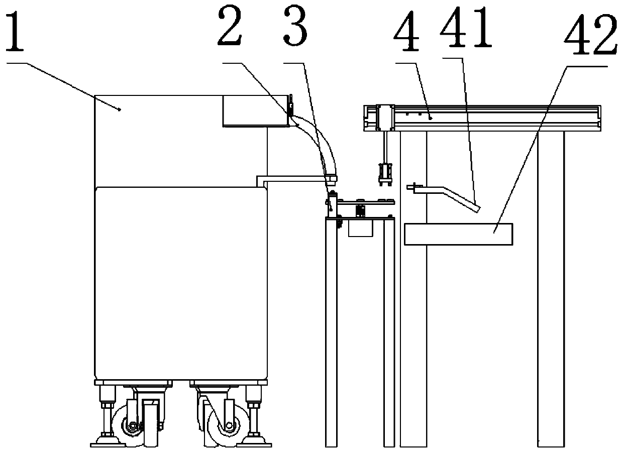
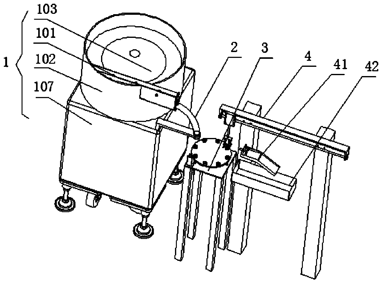
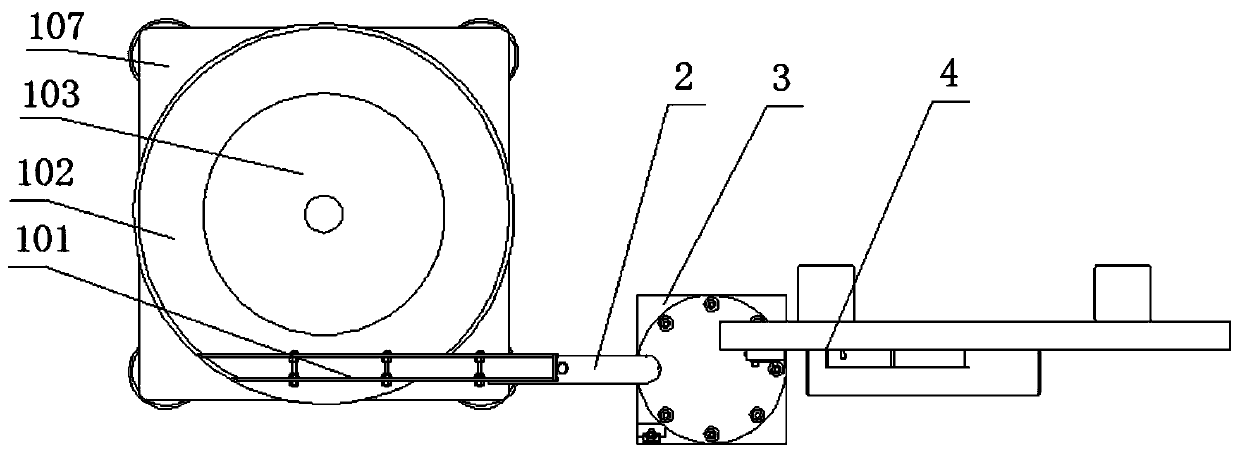
[0035] Such as figure 1 and figure 2 As shown, the embodiment of the present invention provides an automatic cylindrical roller feeding device, including:

[0036] The discharge device 1 is used to neatly arrange a plurality of rollers into the same posture; the screening structure 3 is arranged below the discharge end of the discharge device 1, including: a support structure and a drive structure I, and a motor is selected for the drive structure I. The driving structure I is set on the support structure; the turntable I301 is set above the support structure, and is set and fixed on the output shaft of the drive structure I; the positioning structure is set on the turntable I301, which is used to place the rollers to prevent the rollers from moving; the detection device is set on The supporting structure is used to collect the position and appearance information of the rollers on the turntable I301; the unloading structure 4 is arranged above the turntable I301; and the con...

Embodiment 2

[0038] On the basis of Example 1, such as Figure 4 As shown, wherein, the discharge device 1 selects a discharge device that arranges a plurality of rollers neatly into a horizontal posture, and its specific structure includes a support body 107, and a horizontally arranged turntable II103 is arranged on the top of the support body 107, and the turntable II103 passes through the driving structure. II 106 is driven to rotate, and the drive structure II 106 uses a motor. There is a protrusion in the middle of the turntable II103, and the section of the protrusion is conical. The top is fixed, and the circumferential direction of the baffle 102 is connected with a horizontal track 101. One end of the track 101 communicates with the inner ring of the baffle 102, and the end of the track 101 is located above the turntable I301, that is, when the driving structure II 106 at the bottom of the discharge device 1 is working , so that the rollers in the turntable I301 can enter the tra...

Embodiment 3

[0043] On the basis of Embodiment 1, the discharge device 1 can also be a device that can arrange a plurality of rollers in a vertical posture.


PUM


Abstract

The invention relates to an automatic feeding device for cylindrical rollers. The automatic feeding device comprises a discharging device and a screening structure, wherein the screening structure isarranged below the discharging end of the discharging device and comprises a supporting structure and a driving structure I; the driving structure I is arranged on the supporting structure; a rotary disc I is arranged above the supporting structure and fixed to an output shaft of the driving structure I in a sleeving manner; a positioning structure is arranged on the rotary disc I and used for containing the rollers to prevent the rollers from moving; a detection device is arranged on the supporting structure and used for collecting the position and appearance information of the rollers on therotary disc I; a discharging structure is arranged above the rotary disc I; a controller is used for processing the roller appearance information detected by the detection device and controlling thedischarging structure to screen the rollers according to the processing result; and the controller is electrically connected with the detection device, the discharging structure and the driving structure I. By means of the device, the work efficiency is improved, and the labor cost is reduced.

Description

technical field [0001] The invention relates to the technical field of mechanical automation equipment, in particular to an automatic feeding device for cylindrical rollers. Background technique [0002] Cylindrical rollers are parts of rolling bearings. Spacers or spacers are installed between the rollers of rolling bearings, which can prevent the tilting of the rollers or friction between the rollers, and effectively prevent the increase of rotational torque. Rolling bearings are important machinery. Basic parts are widely used in various fields of national economy and national defense. [0003] At present, the existing automatic assembly system for cylindrical roller bearings has a complex structure, and cannot perform automatic screening and loading of cylindrical rollers, resulting in low loading efficiency of cylindrical rollers and a waste of time for screening qualified rollers, resulting in The problem of low assembly efficiency of sub-bearings, therefore, in view ...

Claims


Application Information

Patent Timeline
IPC IPC(8): F16C43/06B07C5/34B07C5/02
CPCB07C5/02B07C5/34F16C43/06
Inventor 王世伟李淑娟赵恰彭瑞
Owner HUAINAN NORMAL UNIV
Learn More