
Two-dimensional pilot-type electromagnetic cartridge valve

An electromagnetic cartridge valve, pilot-operated technology, applied in valve details, multi-way valves, valve devices, etc., can solve problems such as difficult work, sensitive oil pollution, insufficient valve core thrust, etc., to achieve strong anti-pollution ability, drive The effect of large force and low requirement for filtration precision

Pending Publication Date: 2020-07-28
ZHEJIANG UNIV OF TECH
View PDF0 Cites 4 Cited by
  • Summary
  • Abstract
  • Description
  • Claims
  • Application Information

AI Technical Summary

Problems solved by technology

[0004] In order to overcome the problem that the electromagnetic cartridge valve on the market is limited by the volume and power consumption of the electromagnet, the thrust of the valve core is insufficient, especially difficult to work under high pressure conditions, and sensitive to oil pollution, etc., the present invention proposes a two-dimensional The miniature integrated two-dimensional electromagnetic switch valve is used as a pilot valve to push the two-dimensional pilot electromagnetic cartridge valve to move the valve core. The invention has the advantages of low power consumption of the electromagnet, light weight, fast response, and large direct drive force.

Method used


Image

  • Two-dimensional pilot-type electromagnetic cartridge valve
  • Two-dimensional pilot-type electromagnetic cartridge valve
  • Two-dimensional pilot-type electromagnetic cartridge valve

Examples


Embodiment Construction

[0041] Refer below Figure 1 to Figure 8b The technical scheme of the present invention is further described.

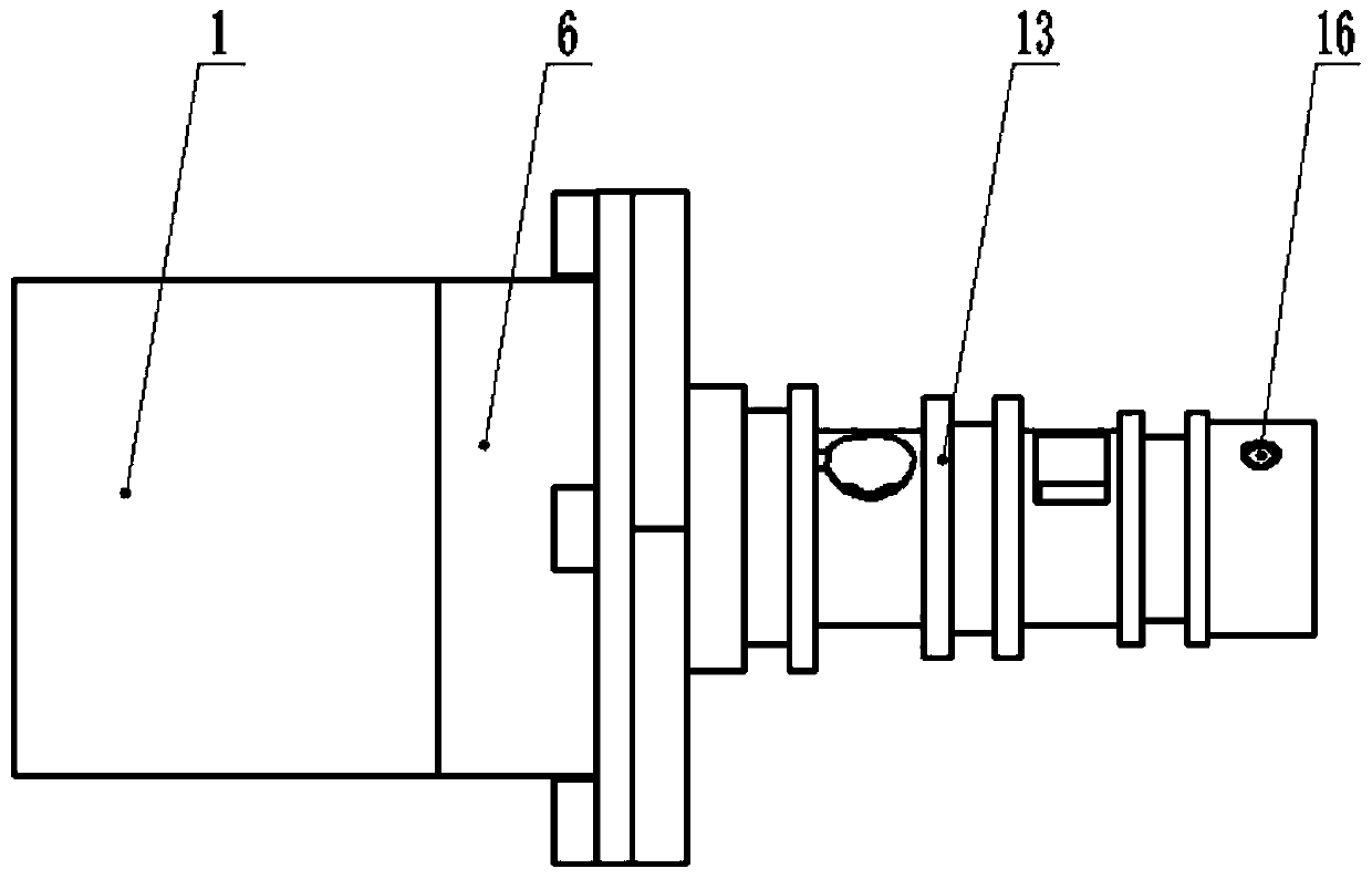
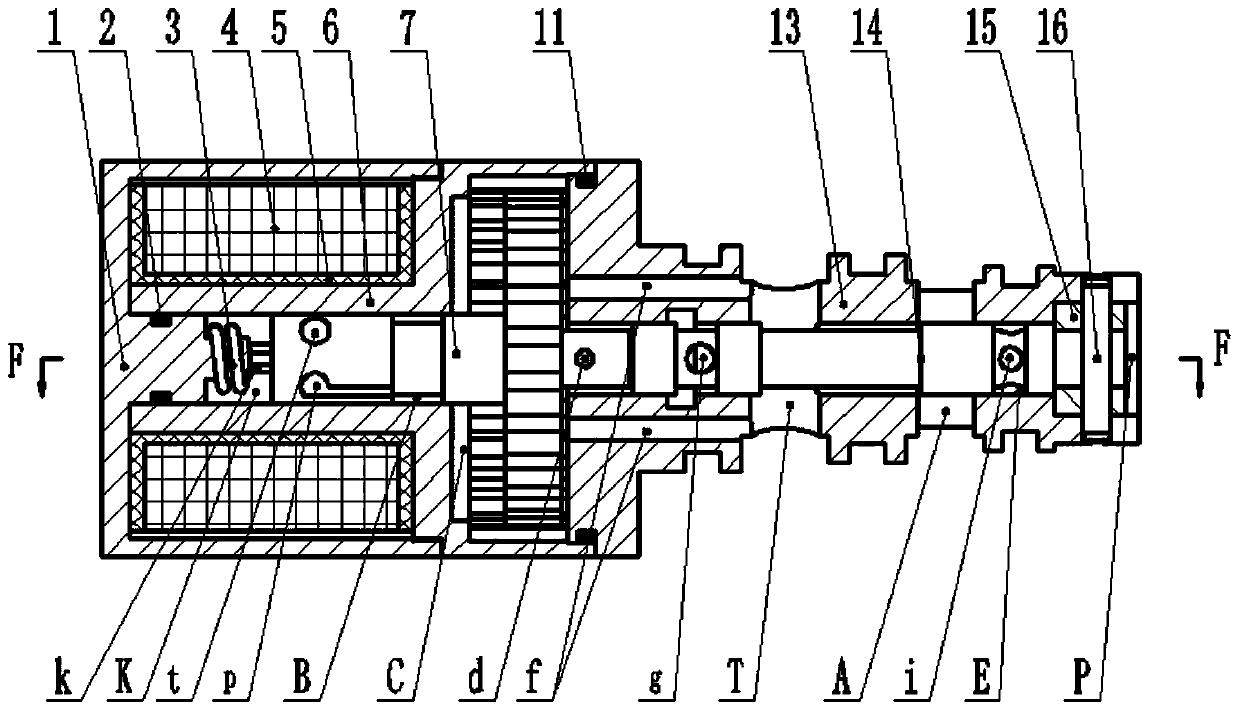
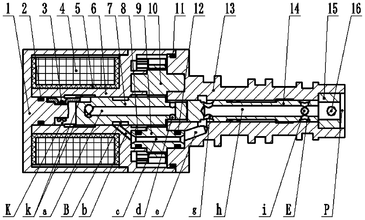
[0042] The two-dimensional pilot-operated electromagnetic cartridge valve is characterized in that it includes a housing 1, a torsion spring 3, a coil 4, a coil holder 5, a stator 6, an armature 7, a first oil guide block 9, and a second oil guide block 10 , Valve sleeve 13, spool 14, limit ring 15, latch 16, etc. One end of the torsion spring 3 is inserted into the slot 101 on the stepped surface of the convex post of the housing 1, and the other end is inserted into the rectangular slot 71 at the left end of the armature 7; the coil 4 is wound on the coil holder 5 and placed on the stator 6, and inserted into the housing 1 together and Fixed, the shell 1 is connected with the stator 6 through threads; one end of the first oil guide block 9 and the second oil guide block 10 are connected with the circular slots 61 and 62 of the stator 6 respectively, and the other ...


PUM


Abstract

The invention discloses a two-dimensional pilot-type electromagnetic cartridge valve. A torsion spring is installed between a shell boss column and an armature; the armature is rotatably arranged in astator; a valve sleeve is connected to the stator; a valve core can axially move and is arranged in the valve sleeve; the right side of the armature is a discoid shape with uniformly distributed external teeth, and the external teeth of the armature are matched with internal teeth of the stator; a first oil guide block and a second oil guide block are inserted into circular through holes of the disc; the center of the first oil guide block is provided with an oil guide flow passage along the axial direction; a stator flow passage communicates with a first high pressure hole of the valve sleeve through the oil guide flow passage, a valve sleeve flow passage, and a first annular groove; the armature is provided with a rectangular clamping groove along the axial direction, and is alternatelyprovided with high-pressure grooves and low-pressure holes; the left end of a first central flow passage in the center of the armature communicates with the low-pressure hole on the right side of thedisc, and the right end communicates with the low-pressure through hole; the valve sleeve flow passage communicates the first annular groove and the oil guide flow passage; the left end surface of the valve sleeve is provided with a low-pressure flow passage communicating with an oil return port along the axial direction; the valve sleeve is sequentially provided with the first annular groove, the oil return port, an oil outlet, and a radial through hole from left to right; and the right end surface of the valve sleeve is provided with an oil inlet.

Description

technical field [0001] The invention belongs to a hydraulic control element in the field of fluid transmission and control, in particular to a two-dimensional pilot electromagnetic cartridge valve. Background technique [0002] In recent years, the two-dimensional electro-hydraulic switching valve using the principle of the servo screw mechanism has dual degrees of freedom of valve core rotation and axial movement, flexible control, high precision, fast frequency response, low hysteresis, small leakage, simple structure, etc. Advantages, currently mainly in aerospace, hydraulic industry and other fields. [0003] In recent years, the hydraulic cartridge valve technology has developed rapidly. The cartridge valve not only changes the system structure of the plate valve from the connection mode, but also has a simple structure, a small footprint, and solves the problem of leakage outside the system. After being widely used, the cartridge valve has gradually formed a series of...

Claims


Application Information

Patent Timeline
Patent Type & Authority Applications(China)
IPC IPC(8): F16K11/065F16K31/06F16K31/40F15B13/02F15B21/08
CPCF16K11/065F16K31/061F16K31/40F15B13/021F15B21/08
Inventor 阮健王熙宋占凯赵建涛郑飞侠孟彬
Owner ZHEJIANG UNIV OF TECH
Learn More